Bi-polymer infrared optics for high-g applications

a high-g, infrared optics technology, applied in the direction of optical elements, instruments, manufacturing tools, etc., can solve the problems of insufficient light weight, insufficient cost, and insufficient cost, so as to achieve high moldability, reduce cost, and reduce cost

Active Publication Date: 2013-08-15
RAYTHEON CO
View PDF1 Cites 33 Cited by
  • Summary
  • Abstract
  • Description
  • Claims
  • Application Information

AI Technical Summary

Benefits of technology

[0005]Aspects and embodiments relate to optical systems, and more specifically to low cost and low mass infrared (IR) optical systems that can withstand operation in high acceleration (high G) and varying temperature environments, such as gun-launched applications, without sacrificing optical quality. Aspects and embodiments address issues identified with previous designs while maintaining a high level of moldability and a relatively low level of assembly complexity.

Problems solved by technology

However, the typical material for the minors and for the structure of the assemblies of these optical systems is aluminum, which requires expensive machining to reach adequate accuracies.
For example, current implementations of gun-launched imaging infrared optics are assembled from conventionally machined aluminum optical components which are both labor and equipment intensive, thereby increasing cost.
Resulting designs are not lightweight enough, nor inexpensive enough, and therefore do not meet the low cost and low mass requirements for such imaging systems.
Previous design attempts reduce mass and cost by molding fiber-reinforced polymer mirrors, but the resulting surface finish is not adequate for use as a minor surface due to the presence of the reinforcing fibers.
On the other hand, design attempts with unreinforced polymers have adequate surface finish, but do not have adequate strength for use in gun-launched systems.
Previous attempts also suffer performance loss from distortion of the optics at high temperature.
Optical distortion at high temperature is due to the difference in coefficients of thermal expansion (CTE) of multiple materials used in the optical system design, as well as due to the difference in CTE between the materials used in the optical system design and the material of an external platform to which the optical system mounts.
However, surface roughness characterization results reveal that as-molded, filled Ultem® polymers are extremely poor candidates for mirror substrates, as their surface roughness is far too high to yield a precision optic.
However, without the filler, the polymer has a much larger CTE as well as lower stiffness and strength.
Therefore, mounting distortion over temperature would result in drastically reduced minor performance, and stress levels during launch shock could induce structural failure.

Method used


Image

  • Bi-polymer infrared optics for high-g applications
  • Bi-polymer infrared optics for high-g applications
  • Bi-polymer infrared optics for high-g applications

Examples


Embodiment Construction

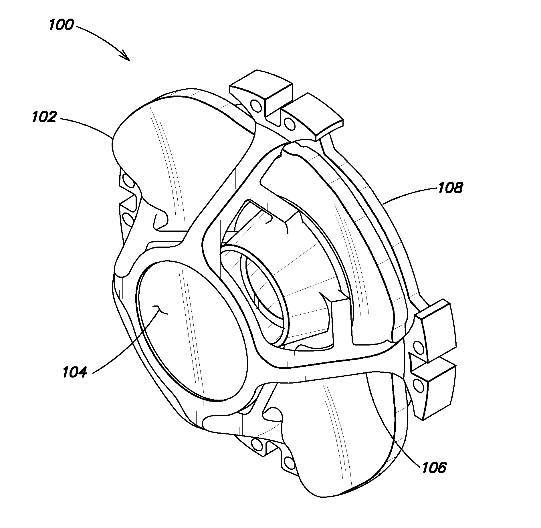
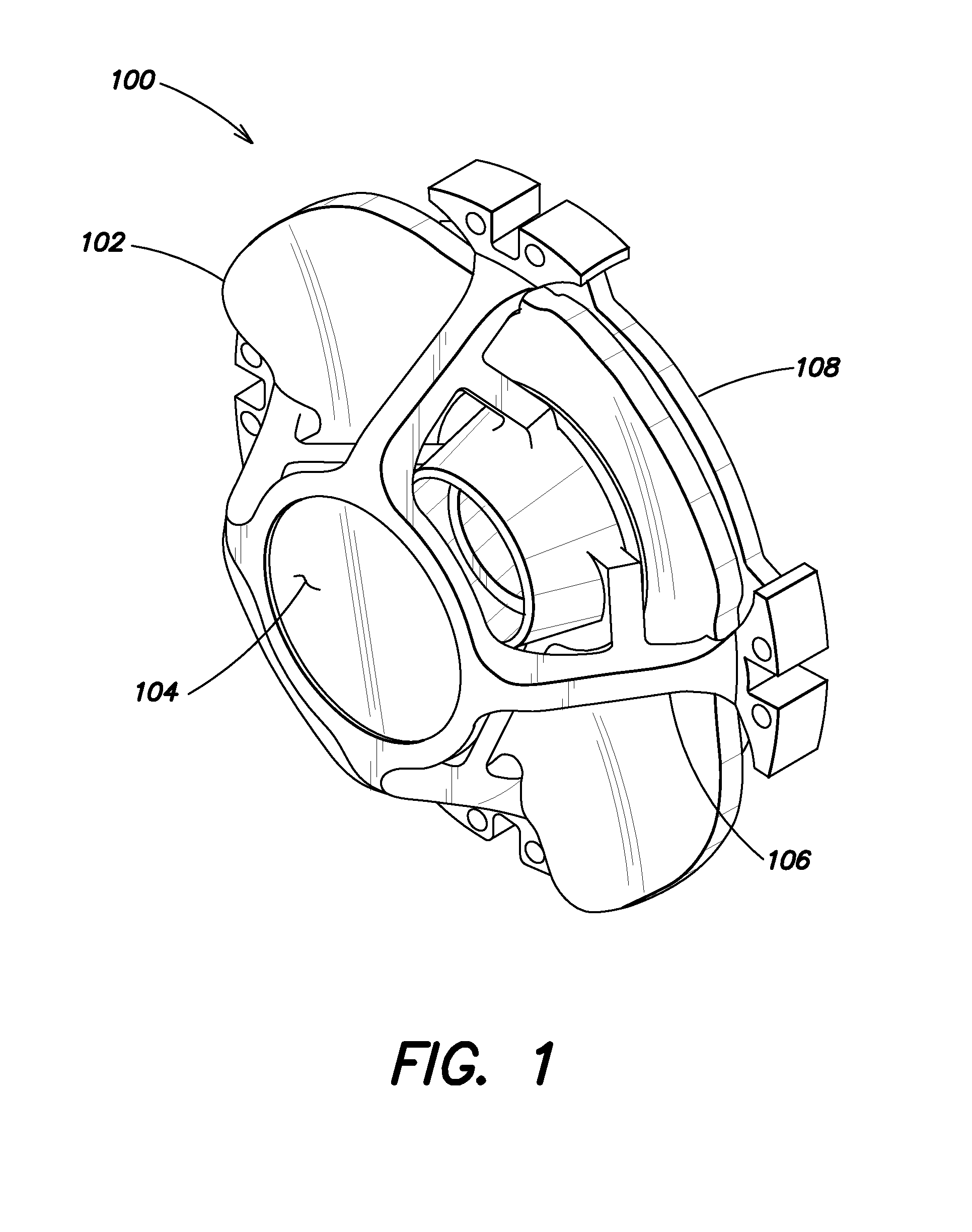
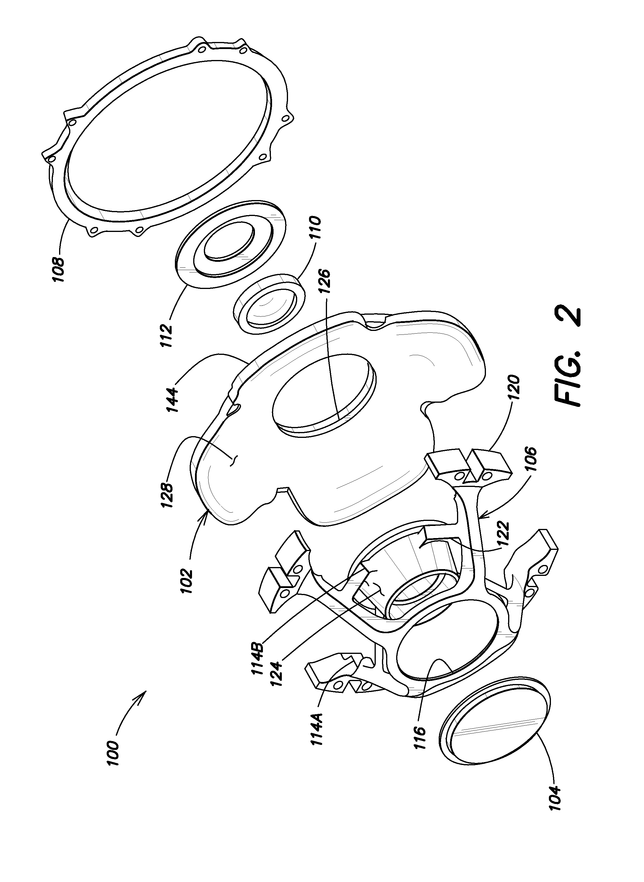
[0029]Aspects and embodiments are directed to providing a low cost and low mass optical apparatus that can survive high acceleration while maintaining optical performance at varying temperatures.

[0030]According to certain embodiments, low cost and low mass are achieved by using inexpensive moldable polymer materials for the optics and for the structural components used in embodiments of the optical apparatus. In some embodiments, the optical apparatus is arranged in a cassegrain or catadioptric optics configuration.

[0031]According to certain aspects, quality of the optics and high G (acceleration) survival of the polymer optical apparatus are simultaneously achieved by segregating the optical and structural functions within embodiments of the optical apparatus. This segregation enables construction of a bi-polymer optical apparatus wherein each of the optics and the structural components are molded from different polymers. For example, in one embodiment, the minors are molded from u...


PUM

PropertyMeasurementUnit
tensile strengthaaaaaaaaaa

Abstract

Optical systems configured to withstand operation in high acceleration and varying temperature environments, and methods of assembling the same. In one example, an imaging optical apparatus includes a primary minor made of an unreinforced polymer, a secondary mirror made of the unreinforced polymer and optically coupled to the primary minor, a field lens optically coupled to the secondary minor, and a strut having a plurality of cross-struts and mounting features configured to mount the primary minor, the secondary mirror and the field lens. In some examples, the imaging optical apparatus further includes an outer retainer disposed behind the primary minor and coupled to the strut, and an inner retainer disposed behind the field lens and coupled to the strut, the outer and inner retainers configured to structurally support the primary minor and the field lens and to accommodate deflections of the primary minor.

Description

FEDERALLY SPONSORED RESEARCH[0001]This invention was made with government support under Grant No. W15QKN-08-C-0054 awarded by the U.S. Department of Defense. The U.S. government has certain rights in this invention.BACKGROUND[0002]Imaging infrared optical systems of a cassegrain or catadioptric form for use in gun-launched applications benefit from low mass components. However, the typical material for the minors and for the structure of the assemblies of these optical systems is aluminum, which requires expensive machining to reach adequate accuracies. For example, current implementations of gun-launched imaging infrared optics are assembled from conventionally machined aluminum optical components which are both labor and equipment intensive, thereby increasing cost. Resulting designs are not lightweight enough, nor inexpensive enough, and therefore do not meet the low cost and low mass requirements for such imaging systems.[0003]Previous design attempts reduce mass and cost by mol...

Claims


Application Information

Patent Timeline
Patent Type & Authority Applications(United States)
IPC IPC(8): G02B17/02B23P25/00
CPCG02B7/008G02B7/182G02B17/0808G02B23/12Y10T29/4998F41G7/2253F41G7/2293F42B15/01G02B23/16
Inventor THOMAS, JOHN A.LIND, THOMAS H.RONCONE, RONALD L.JOHNSON, GARY H.
Owner RAYTHEON CO
Why Eureka
Try Eureka