Bionic eye lens

a bionic lens and eye technology, applied in the field of human vision restoration or improvement, can solve the problems of partial image blur, halo and glare effect, deterioration of the mechanical control of the adaptive lens by the ciliary muscle, etc., and achieve the effect of restoring or improving the quality of human vision

Active Publication Date: 2013-08-22
KATHOLIEKE UNIV LEUVEN
View PDF3 Cites 52 Cited by
  • Summary
  • Abstract
  • Description
  • Claims
  • Application Information

AI Technical Summary

Benefits of technology

[0038]A seventh aspect of the present invention is the provision of a medical device of any one of the first, second, third, fourth, fifth and sixth aspects of the present invention for use in a treatment to restore or improve the quality of human vision.

Problems solved by technology

A standard artificial lens is monofocal and accommodation is no longer possible.
Also, the refractive power of liquid crystal based electro-optic spectacle lenses is polarization dependent, leading to partial image blur and halo and glare effects.
However, it turns out that this system is problematic, because typically for most patients the elasticity of the lens diaphragm is distorted, thus deteriorating the mechanical control of the adaptive lens by the ciliary muscle.
However, no techniques have been proposed to electronically monitor the state of the ciliary muscle.

Method used


Image

  • Bionic eye lens
  • Bionic eye lens
  • Bionic eye lens

Examples


example 1

Novel Artificial Lens (A)

[0129]The novel artificial lens operates electro-optically and comprises a transparent, refractive liquid-crystal display that is AC voltage controlled in order to generate a lens with desired dioptric power.

[0130]A liquid crystal layer is sandwiched between two transparent (e.g. glass or transparent polymer) slides, of which one or both are curved, that are provided by a uniform electrode (indium tin oxide (ITO) electrodes) and a layer of coating to ensure planar alignment (nematic director tangential to the interface) of a liquid crystal without voltage applied on the electrodes. When a voltage is applied on the electrode, the electric field induces locally a change of nematic director towards a more homeotropic alignment (nematic director perpendicular to the interface), thus locally changing the local refractive index for a proper incoming light polarization from a value close to n / / (refractive index value for the electric field component of the electro...

example 2

Novel Conversion Mechanism (B)

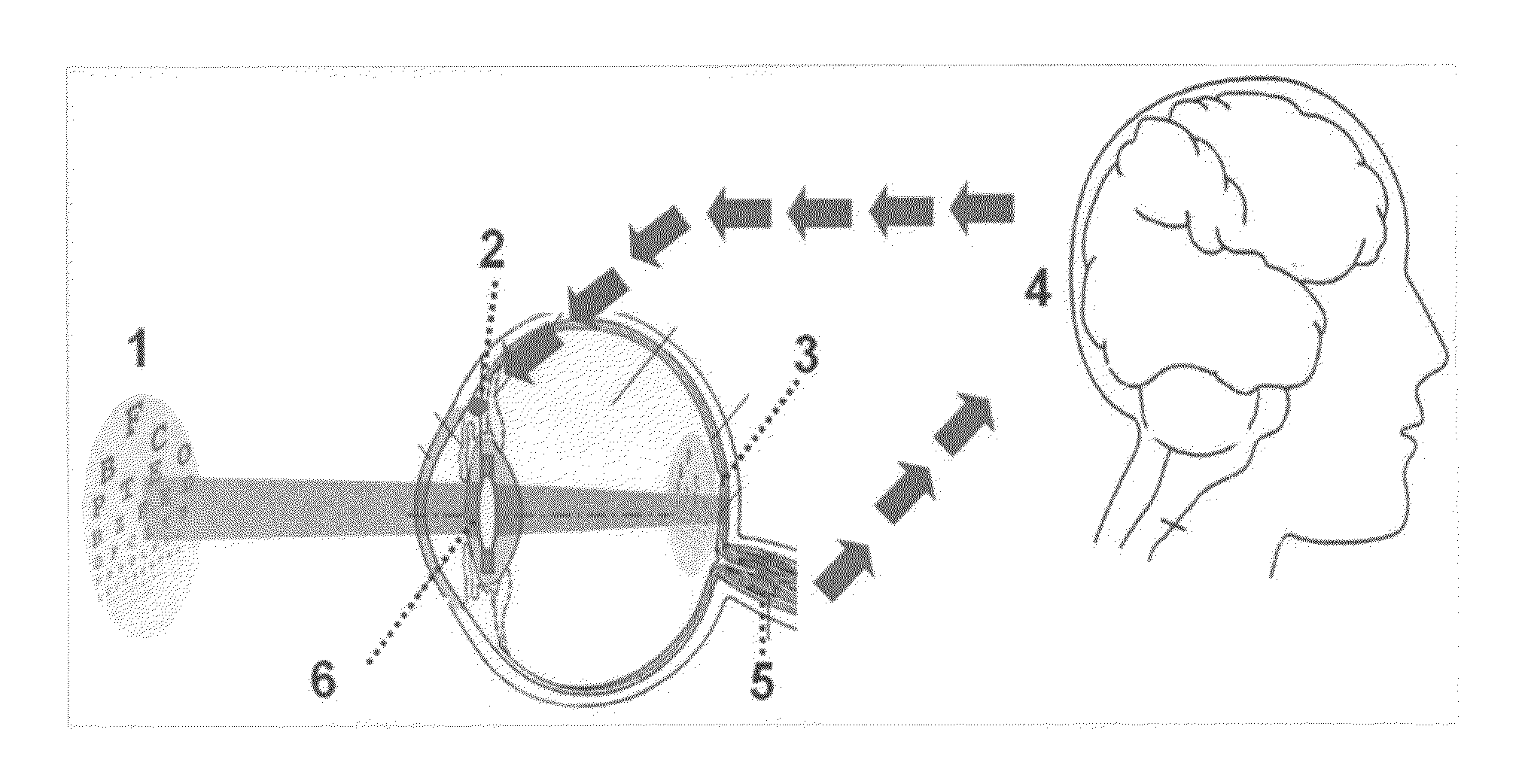
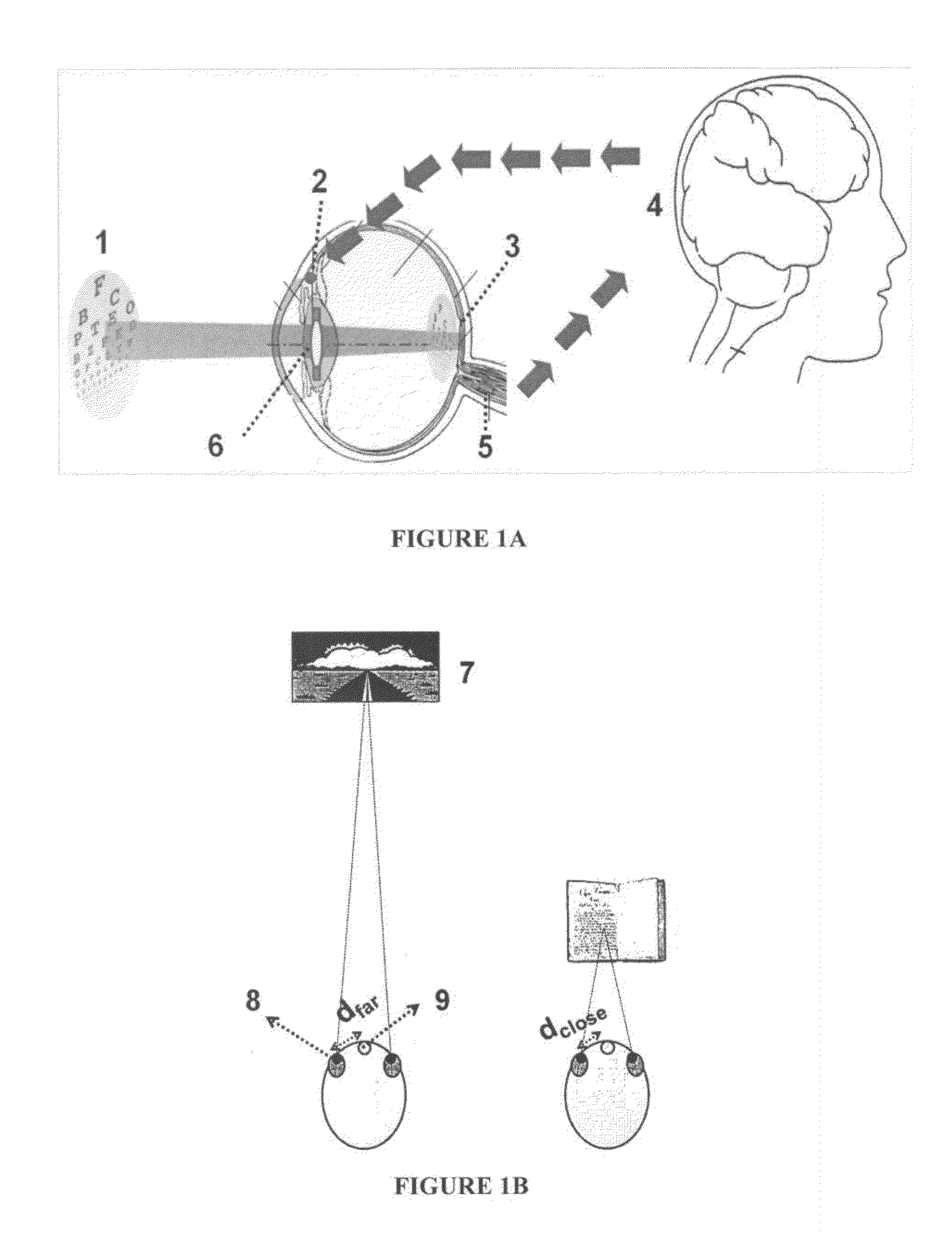
[0136]The second part of the invention consists of a specific way to perform the conversion of the ciliary muscle contraction state changes, which are a measure of how the visual cortex wants to change the focal point of the eye, into a proportional change of voltage signal for steering (by means of direct analogue electronics, or via a digital circuitry including additional signal processing and monitoring) the intra-optical lens, and thus its dioptric strength. Electro-myographic signals from the nerves in or towards the ciliary muscle can be picked up for processing. Electrodes are capable of recording activity from one or a small number of nerve fibers or cell bodies. See, for example, the methods and devices described in U.S. Pat. No. 6,647,296, incorporated herein by reference in its entirety. Electrodes on the scalp or brain surface record from a large number of neurons in aggregation, providing information about the aggregate activity of large p...

example 3

Energy Source (Q)

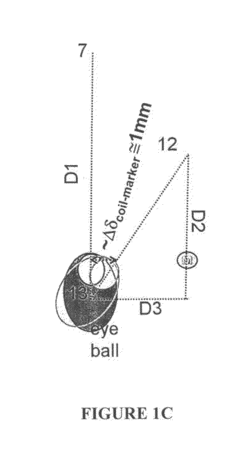
[0137]In a particular embodiment, the electric energy, necessary to drive the electronic detection and driving circuitry, is supplied by a rechargeable battery, which can be charged via a transformer circuit between a receiving coil in the intra-optic lens and a transmitting coil in front of the eye (e.g. in the glasses or pillow of the person). Alternatively, the energy transmission can be achieved by daylight, and if necessary by sending additional, invisible infrared (IR) light from the person's glasses into the eye, to be picked up and converted to electric current in a solar cell placed on the intra-optic device. The electromagnetic interaction between a circuit in front of the person and the intra-optic device can also be used to monitor or the actions of the device, where information is transferred via AM of FM modulation of the electromagnetic waves. External control of the dioptric power of the intra-optic lens offers the possibility to measure the distance...


PUM


Abstract

The present invention relates generally to the restoration or improvement of the quality of human vision and, more particularly to a self-adapting system and method for achieving automatic sharp vision by the human eye of objects for instance at distances between 25 cm and more than 10 meters away. The invention can be situated in at least four technological domains: 1. ophthalmology, in particular the implantation of intraocular lenses. 2. Non-contact biometric signal recording and processing. 3. Electro-optic control of refractive lens power. 4. Wireless energy transfer.

Description

CROSS REFERENCE TO PRIOR APPLICATIONS[0001]This application is a continuation-in-part of International Application PCT / BE2011 / 000045, with an international filing date of Jul. 12, 2011, which claims priority to Great Britain Patent Application No. 1011627.5, filed Jul. 12, 2010, Great Britain Patent Application No. 1104692.7, filed Mar 21, 2011, Land Great Britain Patent Application No. 11045689.3, filed Mar. 21, 2011, the entire contents of which are incorporated herein by reference.FIELD OF THE INVENTION[0002]The present invention relates generally to the restoration or improvement of the quality of human vision and, more particularly to a self-adapting system and method for achieving automatic sharp vision by the human eye of objects for instance at distances between 25 cm and more than 10 meters away.BACKGROUND OF THE INVENTION[0003]Several documents are cited throughout the text of this specification. Each of the documents herein (including any manufacturer's specifications, in...

Claims


Application Information

Patent Timeline
Patent Type & Authority Applications(United States)
IPC IPC(8): A61F2/16
CPCA61B5/1107A61B5/6821A61F2/1627A61B2562/0223A61F2002/1699A61F2250/0002A61F2250/0096
Inventor BLANCKAERT, JOHANGLORIEUX, CHRISTPUERS, ROBERT
Owner KATHOLIEKE UNIV LEUVEN
Why Eureka
Try Eureka