Battery state estimator with overpotential-based variable resistors

a voltage-based variable resistor and state estimator technology, applied in battery/fuel cell control arrangement, instruments, electrochemical generators, etc., can solve the problems of limited computational power, inability to guarantee the accurate estimation of all battery parameters in a complex model with as many frequency modes as possible, and is neither practical nor necessary to cover all frequency modes in one model

Active Publication Date: 2013-08-22
GM GLOBAL TECH OPERATIONS LLC
View PDF1 Cites 33 Cited by
  • Summary
  • Abstract
  • Description
  • Claims
  • Application Information

AI Technical Summary

Benefits of technology

[0010]In accordance with the teachings of the present invention, a battery model and equivalent circuit is disclosed that includes an ohmic resistance, a first RC-pair that models a battery cell charge transfer reaction and double layer processes and a second RC-pair that models battery cell diffusion. Each of the ohmic resistance, the charge transfer reaction resistance and the diffusion resistance in the model are variable resistances, where each resistance changes in response to a change in voltage potential across the resistance.

Problems solved by technology

The reason for this is mainly due to limited computational power and memory available for on-board applications.
In fact, even if there was unlimited computational power and memory, an accurate estimation of all battery parameters in a complex model with as many frequency modes as possible cannot be guaranteed because some information about the full range of dynamic behavior may be lacking from the measured terminal voltage and terminal current for any given level of observed excitation.
Therefore, it is neither practical nor necessary to cover all frequency modes in one model as long as the estimation error caused by model uncertainties is within an acceptable range for a specific application.
However, during certain operating conditions, such as low temperature, high or low battery SOC, etc., the complexity of the actual battery chemistry does not allow the simplified circuit model to accurately represent those conditions.

Method used


Image

  • Battery state estimator with overpotential-based variable resistors
  • Battery state estimator with overpotential-based variable resistors
  • Battery state estimator with overpotential-based variable resistors

Examples


Embodiment Construction

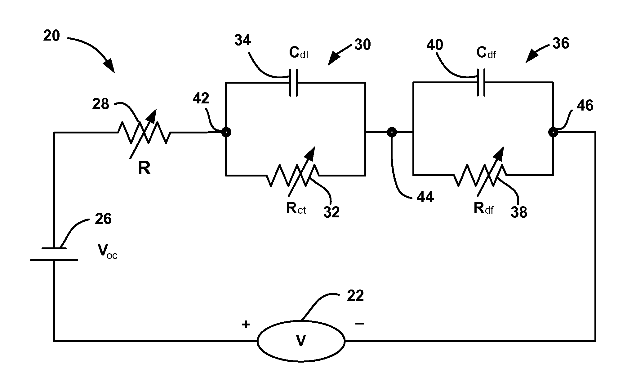
[0014]The following discussion of the embodiments of the invention directed to a battery circuit model including variable resistances based on voltage is merely exemplary in nature, and is in no way intended to limit the invention or its applications or uses. For example, the battery circuit model has particular application for a vehicle battery. However, as will be appreciated by those skilled in the art, the battery model may have application for other types of batteries.

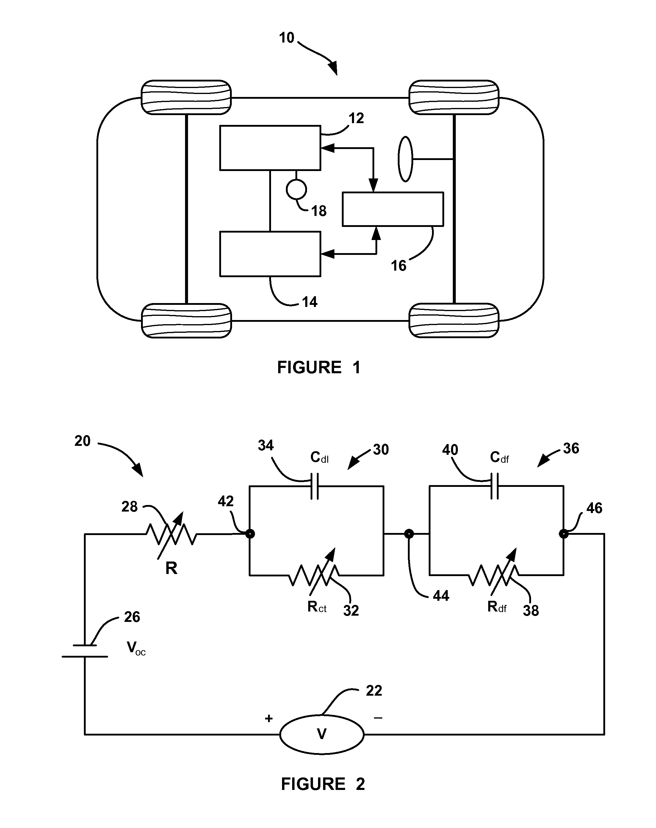
[0015]FIG. 1 is a simplified plan view of a vehicle 10 including a high voltage battery 12 and a main power source 14, where the vehicle 10 is intended to represent any hybrid vehicle, such as hybrid internal combustion engine vehicles, fuel cell system vehicle, etc. The vehicle 10 is also intended to represent any electric only vehicle that only employs a battery as the lone power source. The vehicle 10 includes a controller 16 that is intended to represent all of the control modules and devices necessary for the...


PUM

PropertyMeasurementUnit
voltageaaaaaaaaaa
charge transferaaaaaaaaaa
resistanceaaaaaaaaaa

Abstract

A battery model and equivalent circuit that includes an ohmic resistance, a first RC-pair that models a battery cell charge transfer reaction and double layer processes and a second RC-pair that models battery cell diffusion. Each of the ohmic resistance, the charge transfer reaction resistance and the diffusion resistance in the model are variable resistances, where each resistance changes in response to a change in voltage potential across the resistance.

Description

BACKGROUND OF THE INVENTION[0001]1. Field of the Invention[0002]This invention relates generally to a circuit model for estimating state-of-charge (SOC) for a battery on a vehicle and, more particularly, to a circuit model that estimates state-of-charge for a battery on a vehicle while the vehicle is operating, where resistances within the circuit model are variable based on voltage.[0003]2. Discussion of the Related Art[0004]Electric vehicles are becoming more and more prevalent. These vehicles include hybrid vehicles, such as the extended range electric vehicles (EREV) that combines a battery and a main power source, such as an internal combustion engine, fuel cell system, etc., and electric only vehicles, such as the battery electric vehicles (BEV). All of these types of electric vehicles employ a high voltage battery that includes a number of battery cells. These batteries can be different battery types, such as lithium-ion, nickel metal hydride, lead acid, etc. The battery can ...

Claims


Application Information

Patent Timeline
Patent Type & Authority Applications(United States)
IPC IPC(8): G01R31/36G01N27/416
CPCG01R31/3651G01R31/3662B60L11/1851Y02T10/7011H01M10/48Y02T10/7005Y02T10/705H01M10/052B60L58/10G01R31/367G01R31/389Y02E60/10Y02T10/70G01R31/385G01R31/388
Inventor KOCH, BRIAN J.HARIHARAN, KRISHNAN S.VADIVELU, SENTHIL K.
Owner GM GLOBAL TECH OPERATIONS LLC
Why Eureka
Try Eureka