Distillation tower for improving yield of petroleum hydrocarbon distillate and feeding method thereof

a petroleum hydrocarbon distillate and distillation tower technology, applied in the direction of vacuum distillation separation, hydrocarbon distillation control/regulation, separation processes, etc., can solve the problems of high heat grade of reboiler, difficult to provide with reboiler, and inability to achieve high temperature of heating furnace, so as to increase the fraction oil yield and increase the heat-transfer coefficient and therefore the overall heat-transfer coefficient. , the effect of increasing the fraction oil yield

Active Publication Date: 2013-08-29
RES INST OF PETROLEUM PROCESSING SINOPEC +1
View PDF3 Cites 6 Cited by
  • Summary
  • Abstract
  • Description
  • Claims
  • Application Information

AI Technical Summary

Benefits of technology

[0012]The object of the present invention is to provide a distillation column and a method for improving a fraction oil yield from petroleum hydrocarbons in the distillation column, especially for improving the fraction oil yield in the atmospheric and vacuum distillation column.
[0013]The present invention provides a method for improving a fraction oil yield from petroleum hydrocarbons in the distillation column, wherein said distillation column comprises a vaporization section and a fractionation stage, wherein said method comprises preheating a feedstock oil of petroleum hydrocarbons to be fractionated, sending it through a pressure-feeding system at a pressure of 100-1000 kPa, preferably 200-800 kPa, more preferably 200-600 kPa, and most preferably 200-400 kPa or 200-300 kPa higher than the vaporization section pressure of the distillation column into the vaporization section of the distillation column, atomizing and vaporizing in the vaporization section, and then distillation-separating in the fractionation stage; wherein the fraction oil is removed from column top and / or sideline, and a non-vaporized heavy oil is removed from the column bottom.

Problems solved by technology

For some fractionations of heavy oils, for example, fractionating light fraction oil from crude oil, wax oil and the like, the distillation column generally has a relative high bottom temperature, and the heat source for the reboiler has a high heat grade and is not easy to obtain.
Since heavy oils tend to thermally crack at high temperatures, therefore, the distillation columns for crude oil or heavy oil generally don't provide with reboiler, and the heat required by distillation is almost provided by the feedstocks.
However, the temperature of the heating furnace cannot be too high, this is because it is possible for heavy oils to crack at a temperature higher than 360° C., and the coke produced by cracking the oils will badly influence the long and stable run of the plant.
It is also more and more difficult to improve the performances of the packings and internals, and the cost is sharply increased.
There are also some limitations for using the heating furnace with a furnace tube having a stepwise increased diameter and the oil transfer line with a large diameter.
One limitation is that increasing the diameter of the furnace tube should be designed rationally according to the properties of the feedstock oil and the characteristics of the heating furnace, while it is very hard for a delicate furnace tube design due to a wide variety of feedstocks.
Another limitation is that since a large quantity of feedstock is vaporized in the furnace tube, the density of the feedstock in the tube continuously decreases, especially sharply in a vacuum furnace tube, and therefore the heat-transfer coefficient of the medium in the furnace tube is sharply reduced, which results in the decrease of the overall heat-transfer coefficient in the furnace.
This will lead to a too high topical temperature on the furnace tube wall and influence the use life of the furnace tube.

Method used


Image

  • Distillation tower for improving yield of petroleum hydrocarbon distillate and feeding method thereof
  • Distillation tower for improving yield of petroleum hydrocarbon distillate and feeding method thereof
  • Distillation tower for improving yield of petroleum hydrocarbon distillate and feeding method thereof

Examples


example 1

[0055]Example 1 illustrates the effect of the atmospheric distillation of crude oil according to the method of the present invention.

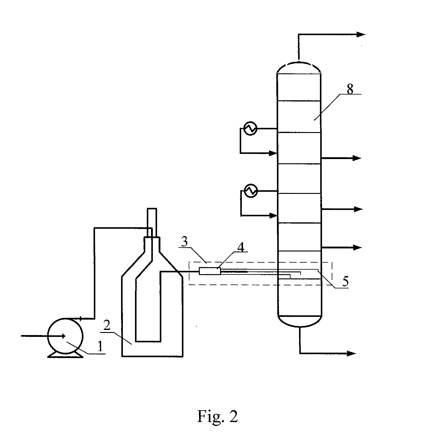
[0056]FIG. 2 is a schematic flow chart for an atmospheric distillation according to the method of the present invention. As shown in FIG. 2, the used atmospheric distillation column 8 was same as that of Comparative Example 1. The feedstock oil to be fractionated was same as that of Comparative Example 1. The feedstock oil, after preheated by the atmospheric heating furnace 2, was ejected to the atmospheric distillation column 8 via a pressure-feeding system (comprising a flow distribution system 4 and atomization devices 5) at a pressure of about 500 kPa higher than the vaporization section pressure of the distillation column. The atmospheric distillation column was provided with the atomization device therein. Said atomization device was a rotary-flow type atomization nozzle. A rotary-flow core was disposed in the front of the nozzle. The top end of ...

example 2

[0060]Example 2 illustrates the effect of the vacuum distillation according to the method of the present invention.

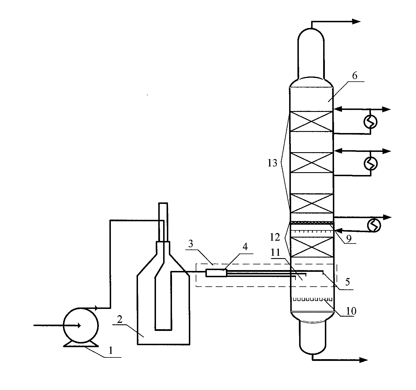
[0061]FIG. 4 is a schematic flow chart for a vacuum distillation according to the method of the present invention. The feedstock oil to be fractionated was atmospheric residue which was same as that used in Comparative Example 2. The feedstock oil was heated by a vacuum heating furnace 2 with a furnace tube diameter of Φ152 mm. The preheated feedstock oil was sent into an oil transfer line, and ejected to the vacuum distillation column 6 via a pressure-feeding system (comprising a flow distribution system 4 and atomization device 5) at a pressure of about 300 kPa higher than the vaporization section pressure of the distillation column. The vacuum distillation column was provided with the atomization device therein as described in Example 1. The operation conditions of the vacuum distillation column and the product properties are shown in Table 4.

TABLE 3The properties of...

example 3

[0066]Example 3 illustrates the effect of the vacuum distillation of crude oil according to the method of the present invention.

[0067]The used atmospheric distillation column system and the mixed crude oil to be fractionated were same as those used in Comparative Example 3. The distillation yield of the atmospheric distillation column was 32 wt %. As shown in FIG. 5, the atmospheric residue from the atmospheric distillation column was sent to a heating furnace 2 of the vacuum distillation system via an oil pump 1, preheated, then ejected into then oil transfer line 7 via a nozzle 5, thoroughly vaporized in the oil transfer line, and then introduced into the vaporization section 8 of the vacuum distillation column via the oil transfer line. The inlet pressure of the oil transfer line was 14.0 kPa, and the inlet temperature was 386° C. The used nozzle is a centrifugal atomization nozzle. The furnace tube of the heating furnace had a constant diameter. The used oil transfer line and va...


PUM

PropertyMeasurementUnit
pressureaaaaaaaaaa
pressureaaaaaaaaaa
pressureaaaaaaaaaa

Abstract

A method for improving yield of petroleum hydrocarbon distillate in a distillation tower (6) comprises: preheating raw oil of petroleum hydrocarbon ready for fractionation; feeding it to a vaporization section (11) through a pressure feed system (3) under a pressure 100-1000 kPa higher than the vaporization section (11) of the distillation tower (6) for simultaneous atomizing and vaporizing; then feeding it to a fractionation section (13) for distillation-separation; and finally, discharging distillate product from the top and / or side of the tower and unvaporized heavy oil from the bottom. A distillation tower (6) for improving yield of petroleum hydrocarbon distillate comprises a vaporization section (11) and a fractionation section (13), and further comprises a pressure feed system (3) for feeding the raw oil of petroleum hydrocarbon ready for fractionation under a pressure 100-1000 kPa higher than that in the vaporization section (11) of the distillation tower (6).

Description

TECHNICAL FIELD [0001]The present invention relates to a distillation column for increasing the fraction oil yield and a method for increasing the fraction oil yield from a distillation column, more particular to a distillation column and a method for increasing the fraction oil yield for the heavy oil distillation in the petroleum refining industry.BACKGROUNDS [0002]The distillation column is a unit device widely used in the petroleum refining industry. For some fractionations of heavy oils, for example, fractionating light fraction oil from crude oil, wax oil and the like, the distillation column generally has a relative high bottom temperature, and the heat source for the reboiler has a high heat grade and is not easy to obtain. Since heavy oils tend to thermally crack at high temperatures, therefore, the distillation columns for crude oil or heavy oil generally don't provide with reboiler, and the heat required by distillation is almost provided by the feedstocks. After preheati...

Claims


Application Information

Patent Timeline
Patent Type & Authority Applications(United States)
IPC IPC(8): C10G7/06
CPCC10G7/00C10G7/12C10G2400/02C10G7/06C10G2300/4025C10G2300/4012C10G2300/1037
Inventor ZHANG, ZHANZHUMAO, JUNYIHOU, SHUANDIQIN, YAYUAN, QINGXU, KEJIAZHANG, TONGWANGWANG, SHAOBINGQU, HONGLIANGTANG, XIAOJINZHU, ZHENXINGHUANG, TAO
Owner RES INST OF PETROLEUM PROCESSING SINOPEC
Why Eureka
Try Eureka