Manufacturing method of optical film and manufacturing method of stereoscopic display

a manufacturing method and technology of a stereoscopic display, applied in the field of manufacturing methods of optical films and stereoscopic display manufacturing methods, can solve the problems of deteriorating the image quality of the stereoscopic display, and achieve the effect of improving the stereo image quality and enhancing the alignment force of reactive liquid crystal materials

Inactive Publication Date: 2013-09-05
CHUNGHWA PICTURE TUBES LTD
View PDF2 Cites 4 Cited by
  • Summary
  • Abstract
  • Description
  • Claims
  • Application Information

AI Technical Summary

Benefits of technology

[0021]Based on the above, in the optical film described in the embodiments, the monomer material is doped into the photo-polymerization alignment material and / or the alignment solution. The monomer material is exposed to the polarized light to form networks on surfaces of the photo-polymerization alignment material and the reactive liquid crystal material. Thereby, the surface anchoring force of the secondary alignment and the alignment force of the reactive liquid crystal material can be enhanced. Namely, the issue of unfavorable secondary alignment can be resolved, and phase retardations at even or odd zones can be equalized. Moreover, owing to the arrangement of the optical film in the stereoscopic display, the color shift problem caused by unfavorable secondary alignment can be solved, and thus the quality of the stereo image can be ameliorated.

Problems solved by technology

However, since the secondary alignment force of the secondary exposure is weaker, which also deteriorates the image quality of the stereoscopic display using the patterned phase retardation film.

Method used


Image

  • Manufacturing method of optical film and manufacturing method of stereoscopic display
  • Manufacturing method of optical film and manufacturing method of stereoscopic display
  • Manufacturing method of optical film and manufacturing method of stereoscopic display

Examples


Embodiment Construction

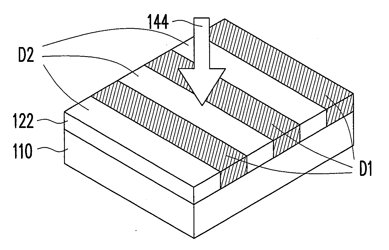
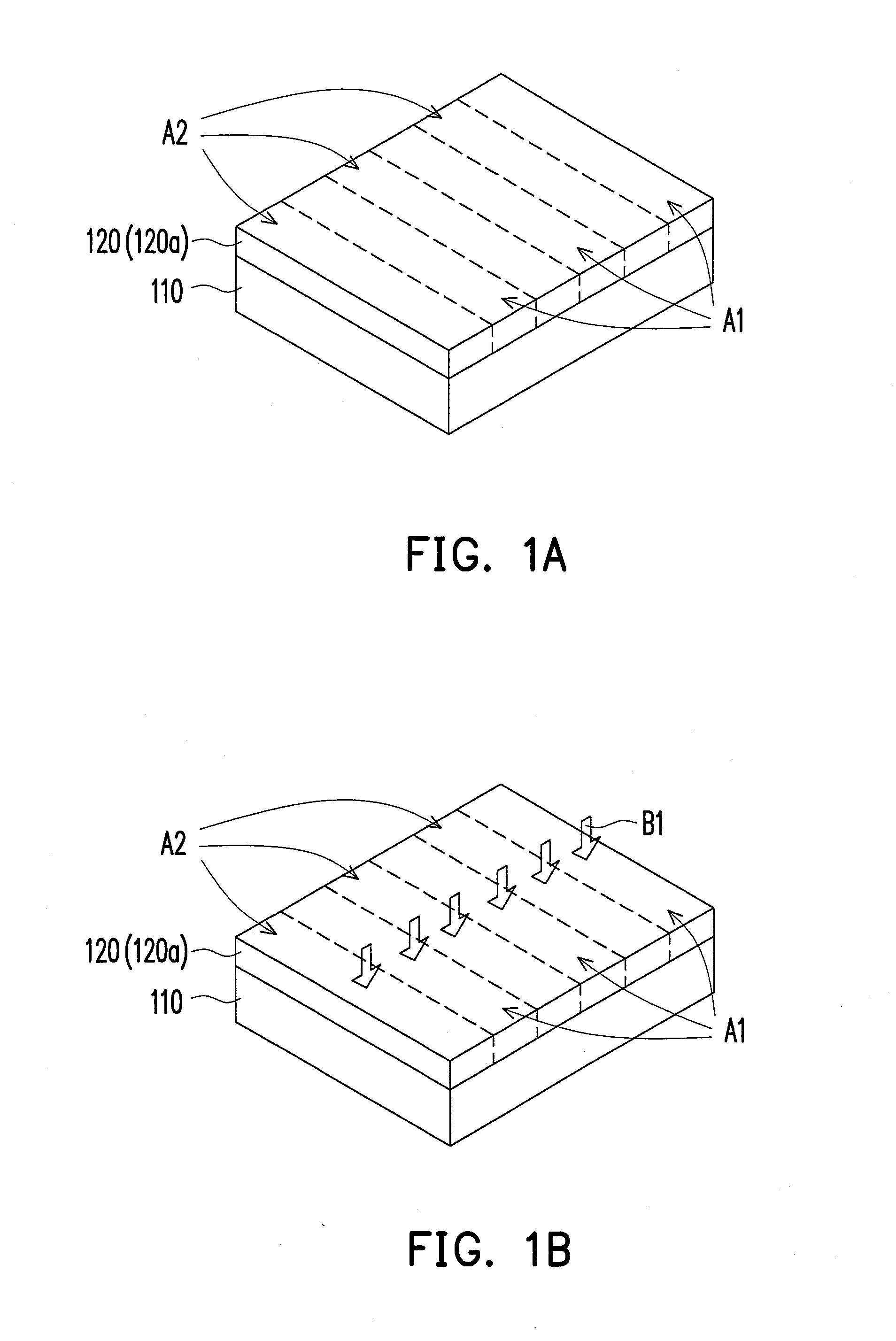
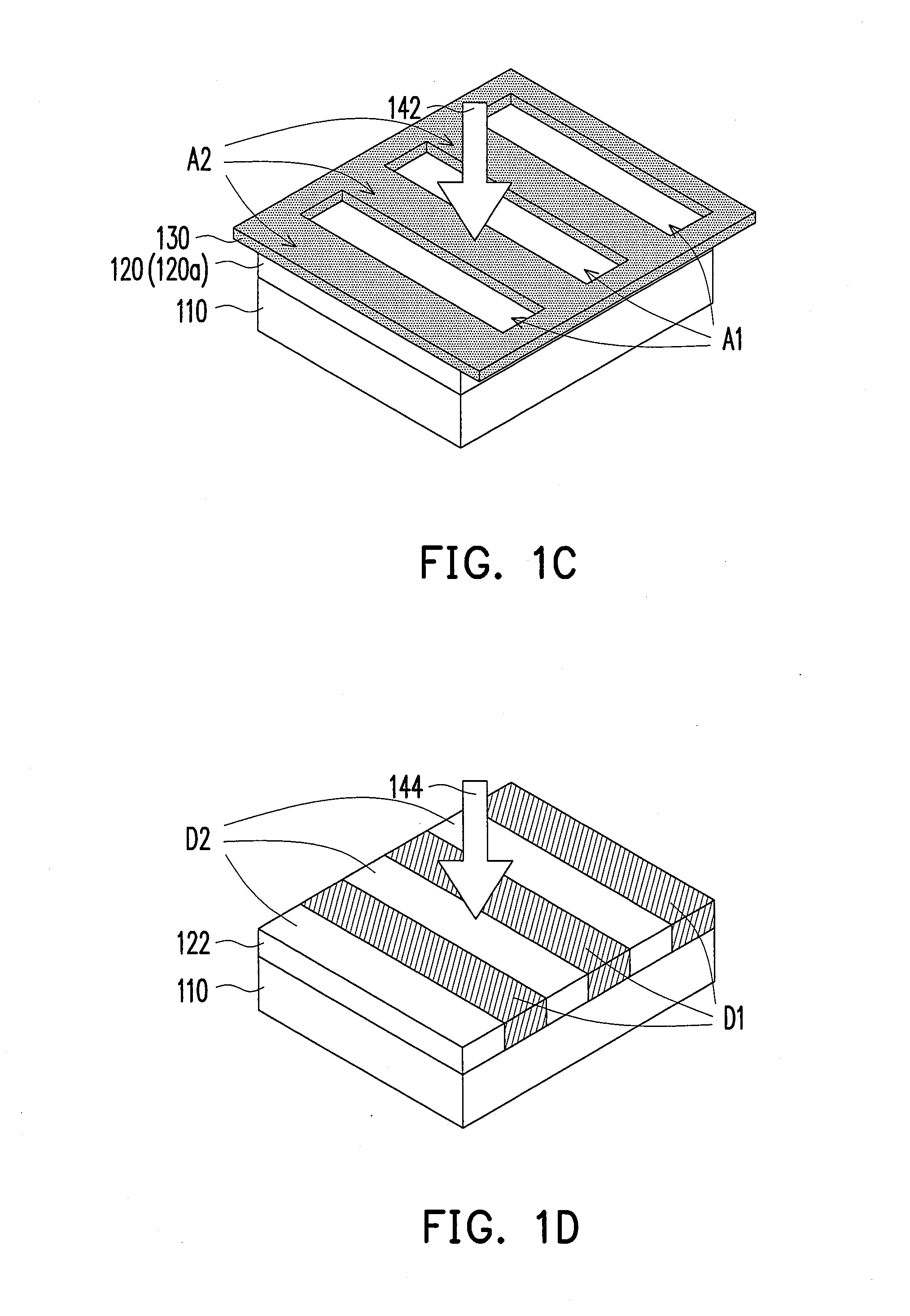
[0029]FIG. 1A to FIG. 1I are schematic side views illustrating a manufacturing process of an optical film according to an embodiment of the invention.

[0030]With reference to FIG. 1A, an alignment solution 120 is coated onto a first substrate 110 which has a first area A1 and a second area A2, and the first area A1 and the second area A2 are alternately arranged. In the present embodiment, the alignment solution 120 may be a photo-polymerization alignment material 120a, but the present invention is not limited thereto. In addition, the alignment solution 120 may be coated onto the first substrate 110 by spin coating, slit coating, or in any other manner well known to people skilled in the art, and thus no further description is provided hereinafter.

[0031]With reference to FIG. 1B, a pre-baking process B1 is performed on the alignment solution 120. Note that the temperature control and the time control of the pre-baking process B1 pose an impact on the subsequent manufacturing process...


PUM

PropertyMeasurementUnit
wavelengthaaaaaaaaaa
absorption wavelengthaaaaaaaaaa

Abstract

A manufacturing method of an optical film includes following steps. An alignment solution is coated onto a first substrate having a first area and a second area. The alignment solution on the first substrate is exposed to a polarized light to form an optical alignment film having a first alignment direction and a second alignment direction on the two areas, respectively. A composite liquid crystal (LC) material containing a reactive LC material and a monomer material is coated onto the optical alignment film. The optical alignment film is sequentially exposed to a first non-polarized light having a monomer material absorption wavelength and a second non-polarized light having a reactive LC material absorption wavelength, thus the monomer material reacts with the reactive LC material, and the reactive LC material is solidified along the first and second alignment directions in sequence. A manufacturing method of a stereoscopic display is also provided.

Description

CROSS-REFERENCE TO RELATED APPLICATION[0001]This application claims the priority benefit of Taiwan application serial no. 101107180, filed on Mar. 3, 2012. The entirety of the above-mentioned patent application is hereby incorporated by reference herein and made a part of this specification.BACKGROUND OF THE INVENTION[0002]1. Field of the Invention[0003]The invention relates to a manufacturing method of a film and a manufacturing method of a display. More particularly, the invention relates to a manufacturing method of an optical film and a manufacturing method of a stereoscopic display.[0004]2. Description of Related Art[0005]In recent years, the continuing progress of display technologies leads to increasing demands on display quality of displays (e.g., image resolution, color saturation, and so on). However, other than the requirements for high resolution and high color saturation, in order to satisfy the need of users to watch real images, stereo displays which are capable of di...

Claims


Application Information

Patent Timeline
Patent Type & Authority Applications(United States)
IPC IPC(8): B05D3/06B23P17/04B05D1/32
CPCB23P17/04Y10T29/49885G02B27/2214G02B30/25G02B30/30G02B30/27
Inventor SU, CHUN-WEILIEN, JAN-TIEN
Owner CHUNGHWA PICTURE TUBES LTD
Why Eureka
Try Eureka