System, method & device for UV curing

a technology of uv curing and system, applied in the direction of fibre light guide, nuclear engineering, therapy, etc., can solve the problems of increasing signal attenuation, experiencing non-uniform forces, accelerating aging and deterioration of fiber strength, etc., and achieve the effect of low operating cos

Inactive Publication Date: 2013-09-05
NIEMINEN KARI
View PDF2 Cites 22 Cited by
  • Summary
  • Abstract
  • Description
  • Claims
  • Application Information

AI Technical Summary

Benefits of technology

[0040]Another aspect of the technology disclosed herein is that it eliminates the need for separate reflectors (light emitting points are located in proximity to the fiber and the UV light is optically focused to a narrow beam, with the beam being slightly larger than the targeted coated fiber itself; the excess minor portion of the light beam could be reflected towa

Problems solved by technology

Unevenly coated fiber will experience non-uniform forces when the coating expands or contracts, and is susceptible to greater signal attenuation.
The combination of moisture and scratches accelerates the aging and deterioration of fiber strength.
When fiber is subjected to low stresses over a long period, fiber fatigue can occur.
Over time or in extreme conditions, these factors combine to cause microscopic flaws in the glass fiber to propagate, which can ultimately result in fiber failure.
This process shrinks the initial application of coatings by more than 50% and creates environmental pollutants.
However current systems are using special bulbs that are very inefficient in producing the necessary UV power.
Furthermore, the thin metallic reflectors used are subject to high temperature (which ma

Method used


Image

  • System, method & device for UV curing
  • System, method & device for UV curing
  • System, method & device for UV curing

Examples


Embodiment Construction

[0052]In describing the preferred and other embodiments of the technology described herein, as illustrated in FIGS. 1-6, specific terminology is employed for the sake of clarity. The invention, however, is not intended to be limited to the specific terminology so selected, and it is to be understood that each specific element includes all technical equivalents that operate in a similar manner to accomplish similar functions.

[0053]Referring now to FIGS. 1-7, illustrated therein is a device, method and system for providing a system, method and devices for an improved way to harden UV-curable coating materials that have been applied to optical fibers.

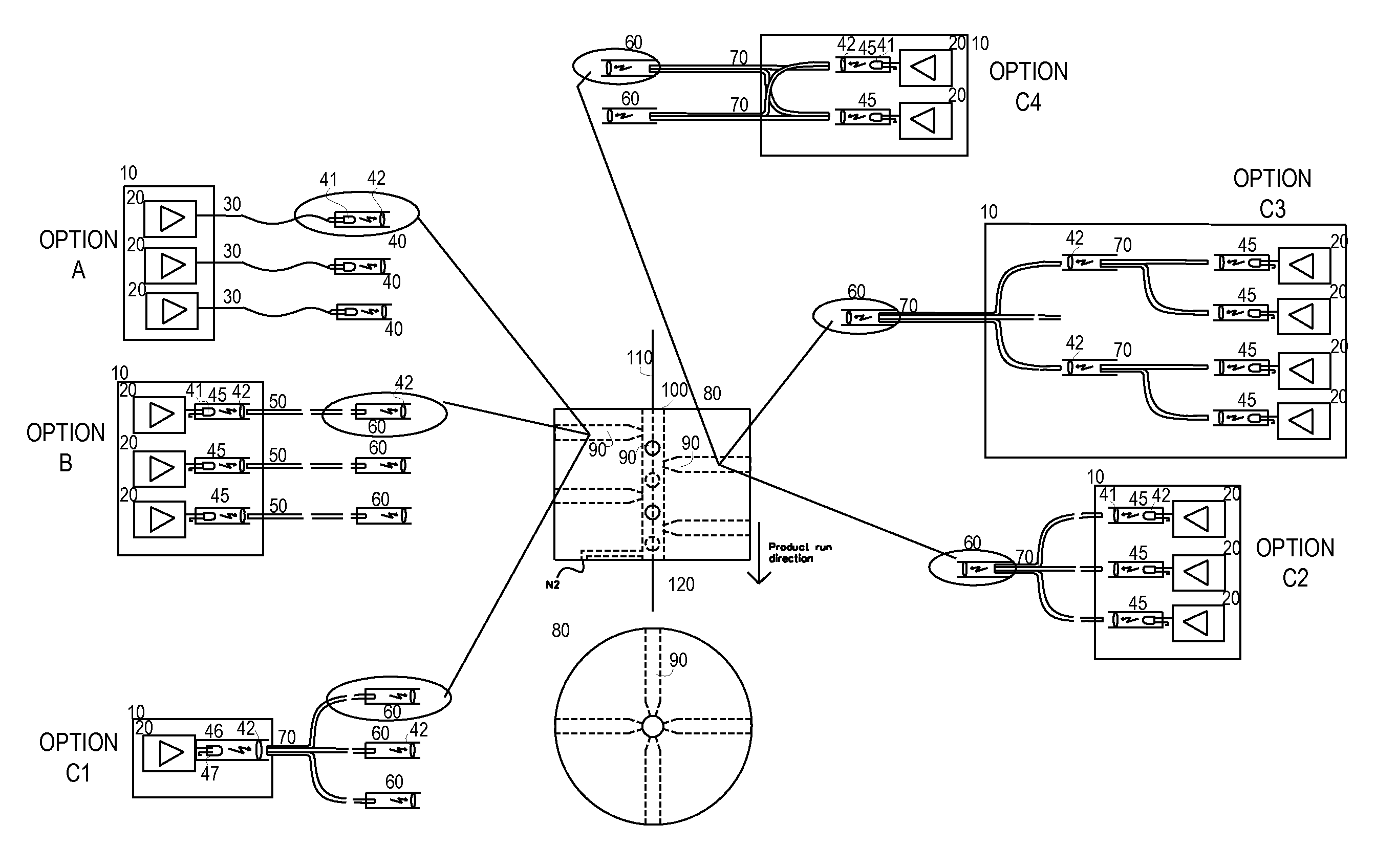
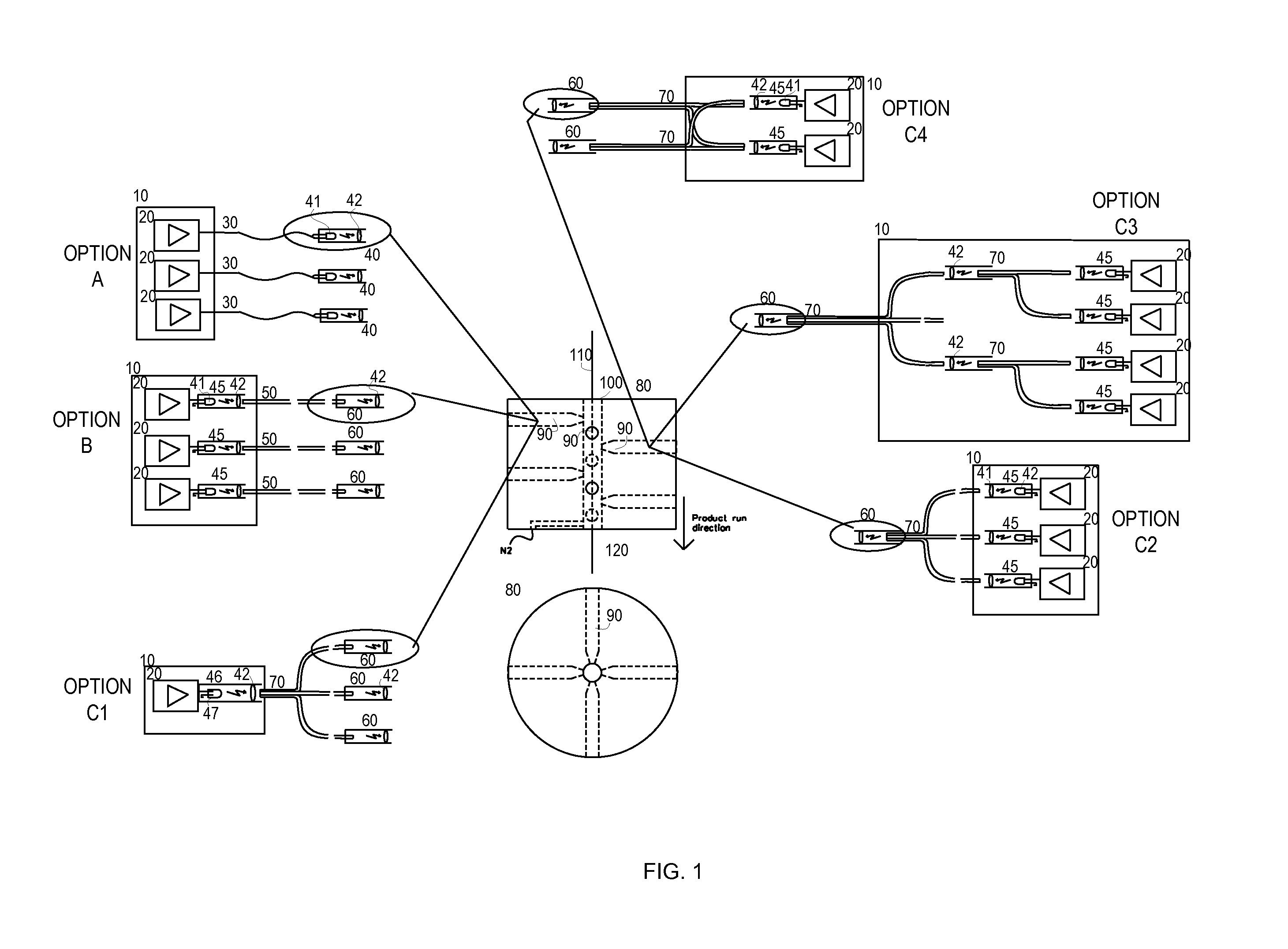
[0054]FIG. 1 option A illustrates a configuration for a UV curing chamber, according to the first exemplary embodiment of the technology;

[0055]In the option A embodiment the technology described herein comprises:[0056]an electrical control unit (10) that feeds electrical power to light sources; conducts on / off control; regulates output pow...


PUM

PropertyMeasurementUnit
Angleaaaaaaaaaa
Poweraaaaaaaaaa

Abstract

A system, method and devices for providing improved methods to harden UV-curable coating materials when those coating materials are applied over optical fibers or other optical targets during the manufacturing process is provided. The technology disclosed herein uses LEDs (or low power light bulbs) to create UV power, which is focused with high intensity on the surface of a coated fiber. This is done simultaneously from multiple angles to fully cover the target product over 360 degrees of surface and is then repeated a number of times along the product path to ensure sufficient degree of curing.

Description

FIELD OF THE INVENTION[0001]The technology described herein relates generally to a system, method and devices for an improved way to harden UV-curable coating materials that have been applied to optical fibers.BACKGROUND OF THE INVENTION[0002]Fiber optic coatings are applied using one of two methods: wet-on-dry and wet-on-wet.[0003]In wet-on-dry, the fiber passes first through a primary coating application, which is then UV cured, then passes through a secondary coating application, which is subsequently cured.[0004]In wet-on-wet, the fiber passes through both the primary and secondary coating applications, then the fiber proceeds to UV curing.[0005]Fiber optic coatings are applied in concentric layers to prevent damage to the fiber during the drawing application and to maximize fiber strength and microbend resistance. Unevenly coated fiber will experience non-uniform forces when the coating expands or contracts, and is susceptible to greater signal attenuation. Under proper drawing...

Claims


Application Information

Patent Timeline
IPC IPC(8): B01J19/12
CPCB05D3/067G02B6/0008B05D2256/00B05D7/20C03C25/12
Inventor NIEMINEN, KARI
Owner NIEMINEN KARI
Why Eureka
Try Eureka