Wireless power transfer system and wireless power transfer method

a power transfer system and wireless technology, applied in the direction of inductance, transportation and packaging, rail devices, etc., can solve the problems of short power transmission distance, technique does not solve variations in power transfer efficiency, and causes dielectric loss, etc., to increase the possible power transfer area, suppress variations in transfer efficiency, and improve the effect of power transfer efficiency

Inactive Publication Date: 2013-09-12
HITACHT MAXELL LTD
View PDF14 Cites 252 Cited by
  • Summary
  • Abstract
  • Description
  • Claims
  • Application Information

AI Technical Summary

Benefits of technology

[0012]It is also an object of the present invention to provide a wireless power transfer system and a wireless power transfer method capable of performing power transfer with stable efficiency without providing an adjusting circuit in a power receiver, while involving a displacement or a rotation of the power receiver.
[0016]According to the present invention, by placing the power receiving coil in the power receiving space between the power transmission coil and the auxiliary coil, while allowing the power receiving coil to displace or rotate, it is possible to increase the possible power transfer area between the power transmission coil and the power receiving coil in comparison with the case of arranging the power transmission coil alone. Therefore, power transfer can be performed with stable efficiency by suppressing variations in transfer efficiency resulting from movements of the power receiving coil.
[0017]Moreover, since the control for achieving high power transfer efficiency is simple, the cost of the wireless power transfer system can be reduced.
[0018]Further, even when the power receiving coil is smaller than the power transmission coil in size, declines in the power transfer efficiency, the possible power transfer distance, and the like can be reduced, so that power can be transferred with stable efficiency without providing the power receiver with a device for adjusting resonance frequencies. Consequently, the cost of the power receiver can be reduced.

Problems solved by technology

Although this method is advantageous, for example, in that it can be realized with simple circuitry (a transformer), it also has the problem of a short power transmission distance.
Among them, in the electric field resonance type method, when placing the hand or the like in a transfer path, a dielectric loss is caused, because the human body, which is a dielectric, absorbs energy as heat.
However, this technique does not resolve variations in power transfer efficiency resulting from differences in distance between the ground (power transmission coil) and power receiving coils, which come from differences in size, shape, etc. among vehicles (e.g., a sport car and a large truck).
Further, if the power receiving coil is smaller than the power transmission coil, the power transfer efficiency, the possible power transfer distance and the like can decline, regardless of differences among vehicles.
Furthermore, variations in coupling coefficient caused by changes in conditions such as the distance between the power transmission coil and the power receiving coil cause a decline in the power transfer efficiency.

Method used


Image

  • Wireless power transfer system and wireless power transfer method
  • Wireless power transfer system and wireless power transfer method
  • Wireless power transfer system and wireless power transfer method

Examples


embodiment 1

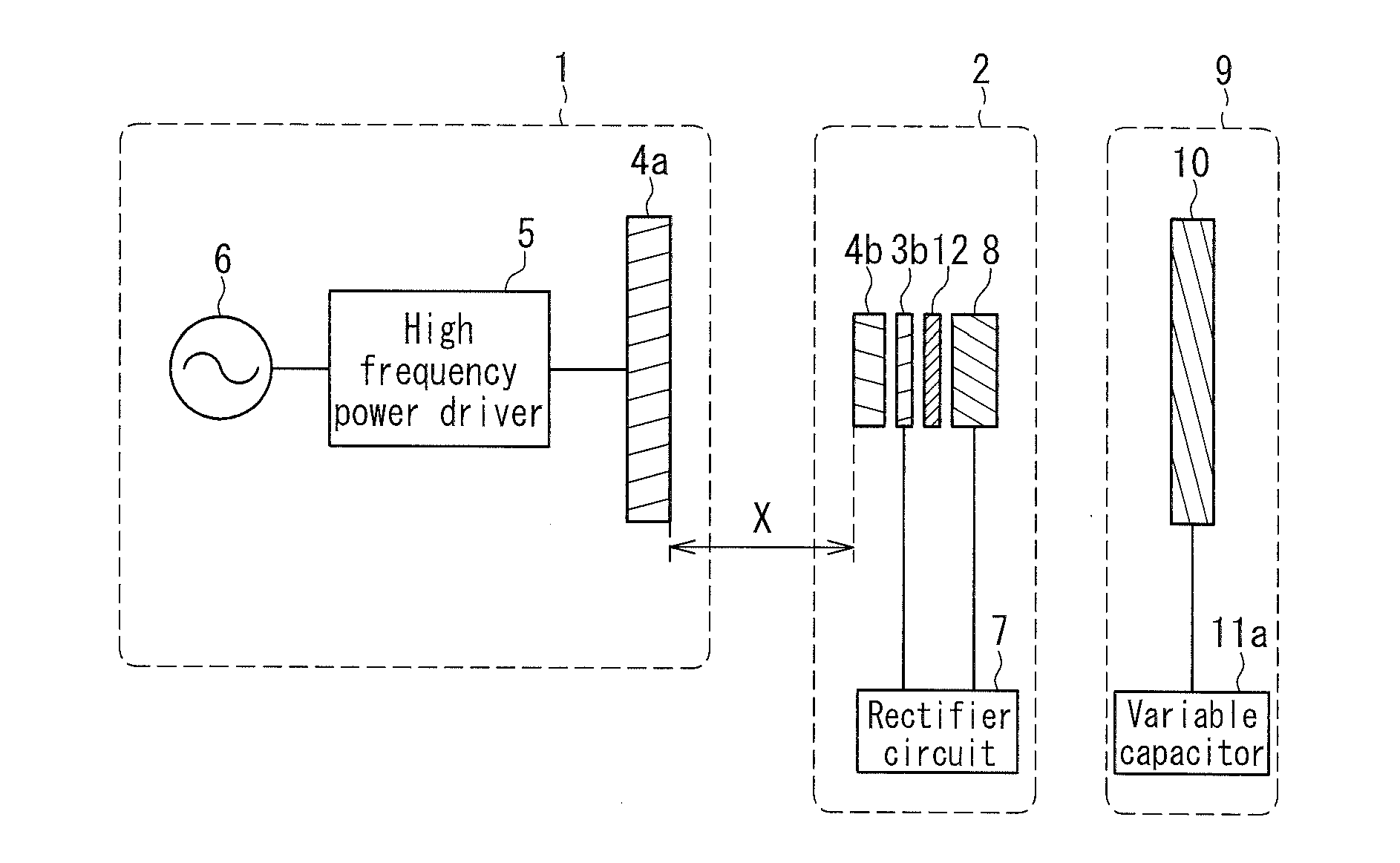
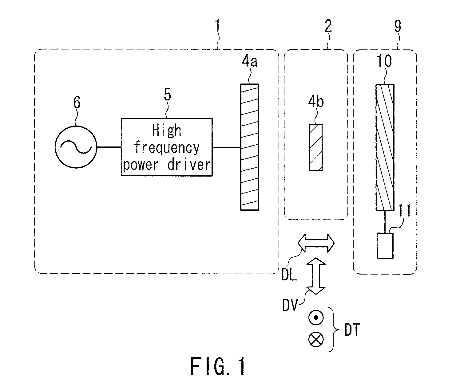
[0062]FIG. 1 is a schematic cross-sectional view showing the configuration of a wireless power transfer system of a magnetic field resonance type according to Embodiment 1. The present embodiment illustrates the basic concept of the wireless power transfer system of the present invention. Note that the same elements as those of the conventional wireless power transfer system shown in FIG. 20 are denoted by the same reference numerals, and the description thereof will not be repeated.

[0063]This wireless power transfer system includes a power transmission auxiliary device 9 in addition to the power transmitter 1 and the power receiver 2 of conventional technology, and is configured to perform wireless power transfer in a state in which the power receiver 2 is placed in a space between the power transmitter 1 and the power transmission auxiliary device 9. The power transmitter 1 converts power of an AC power supply (AC 100 V) into transferable high frequency power, and transfer the pow...

embodiment 2

[0100]The basic configuration of a wireless power transfer system according to Embodiment 2 will be described with reference to FIGS. 8A to 8C. FIGS. 8A to 8C are schematic cross-sectional views showing the configuration and operation of the wireless power transfer system according to the present embodiment. That is, from FIG. 8A to FIG. 8C show an exemplary operation where a power receiver travels in one direction. In order to facilitate understanding of the illustrations in these drawings, a power transmission coil included in a power transmission device, an auxiliary coil included in a power transmission auxiliary device, and a power receiving coil included in a power receiver are shown schematically. The same goes for the embodiments described later.

[0101]In the configuration shown in FIGS. 8A to 8C, a power transmission coil 13, an auxiliary coil 14, a power transmission coil 15, and an auxiliary coil 16 are arranged in order along their axial direction. The power transmission ...

embodiment 3

[0121]The basic configuration of a wireless power transfer system according to Embodiment 3 will be described with reference to FIGS. 11A to 11C. FIGS. 11A to 11C are schematic cross-sectional views showing the configuration and operation of the wireless power transfer system according to the present embodiment. From FIG. 11A to FIG. 11C show an exemplary operation in which a power receiver travels in one direction.

[0122]In the configuration of FIGS. 11A to 11C, a power transmission coil 29 and an auxiliary coil 30, a power transmission coil 31 and an auxiliary coil 32, and a power transmission coil 33 and an auxiliary coil 34 are in pairs, opposing each other, and the pairs form three power receiving spaces E to G. That is, one power receiving space is formed by a pair of opposing power transmission and auxiliary coils and the power receiving spaces E to G are arranged in sequence in the direction perpendicular to the axis of each power transmission coil.

[0123]In the power receivin...


PUM


Abstract

A wireless power transfer system includes a power transmitter including a power transmission resonator composed of a power transmission coil and a resonant capacitance; and a power receiver including a power receiving resonator composed of a power receiving coil and a resonant capacitance. The system further includes a power transmission auxiliary device including an auxiliary resonator composed of an auxiliary coil and a resonant capacitance. The power transmission auxiliary device and the power transmission device oppose each other, forming a power receiving space for placing the power receiving coil between the power transmission coil and the auxiliary coil, and power transfer is performed in the power receiving space while involving a movement of the power receiving coil including at least one of a displacement and a rotation. The power transfer can be performed with stable efficiency in spite of the movement of the power receiver.

Description

BACKGROUND OF THE INVENTION[0001]1. Field of the Invention[0002]The present invention relates to a wireless power transfer system and a wireless power transfer method for wireless power transfer via a power transmission coil provided in a power transmitter and a power receiving coil provided in a power receiver.[0003]2. Description of Related Art[0004]As wireless power transfer methods, an electromagnetic induction type (several hundred kHz), electric or magnetic-field resonance type using transfer based on LC resonance through electric or magnetic field resonance, a microwave transmission-type using radio waves (several GHz), and a laser transmission-type using electromagnetic waves (light) in the visible radiation range are known. Among them, the electromagnetic induction type has already been used practically. Although this method is advantageous, for example, in that it can be realized with simple circuitry (a transformer), it also has the problem of a short power transmission d...

Claims


Application Information

Patent Timeline
Patent Type & Authority Applications(United States)
IPC IPC(8): H02J17/00B60L5/00B60M7/00
CPCH02J17/00H02J5/005H02J50/12H02J50/70H02J50/40H02J50/90
Inventor MIYAUCHI, YASUSHI
Owner HITACHT MAXELL LTD
Why Eureka
Try Eureka