Electro-optic communications device with frequency conversion and related methods

Active Publication Date: 2013-09-12
HARRIS CORP
View PDF3 Cites 35 Cited by
  • Summary
  • Abstract
  • Description
  • Claims
  • Application Information

AI Technical Summary

Benefits of technology

[0007]In view of the foregoing background, it is therefore an object of the present invention to

Problems solved by technology

For example, transmission of the signals over coaxial cable may incur large attenuation effects.
Moreover, in applications where RF devices are used, the size, weight, and power (SWaP) of the components may increase to undesirable levels.
Moreover, downstream receiver processing, such as downconverting,

Method used


Image

  • Electro-optic communications device with frequency conversion and related methods
  • Electro-optic communications device with frequency conversion and related methods
  • Electro-optic communications device with frequency conversion and related methods

Examples


experiment conclusion

[0047]A photonic frequency converter based on optical sideband filtering can be used to produce up- and down-converted signals over a wide range of RF frequencies. The reduction of mixing spurs provides an additional advantage over conventional RF mixers. Down-conversion was demonstrated from 5-20 GHz to a 100 MHz IF with positive gain and high linearity. Direct digitization of downconverted RF signals at 10 and 20 GHz with negligible degradation of ADC performance is provided. The disclosed approach also showed reduced phase noise for an up-converted RF signal. The sideband-filtered method produces a signal with phase noise limited by the LO signal generator.

Supplemental Experimental Results

[0048]Referring specifically to FIG. 8-9, diagrams 80 and 85 illustrate performance of where the optical power is 5 W, the local oscillator input power is 20 dBm, the DC photocurrent is 20 Ma, and the FBG bandwidth is 5 GHz. Curve 81 shows measured noise floor, and curve 86 shows spurious free d...


PUM


Abstract

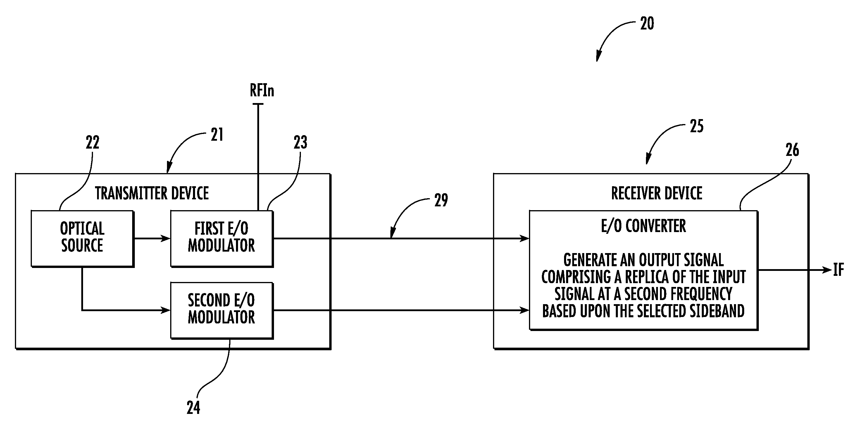
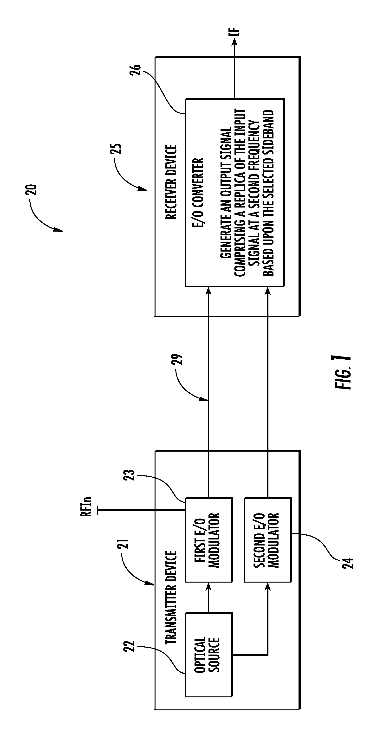
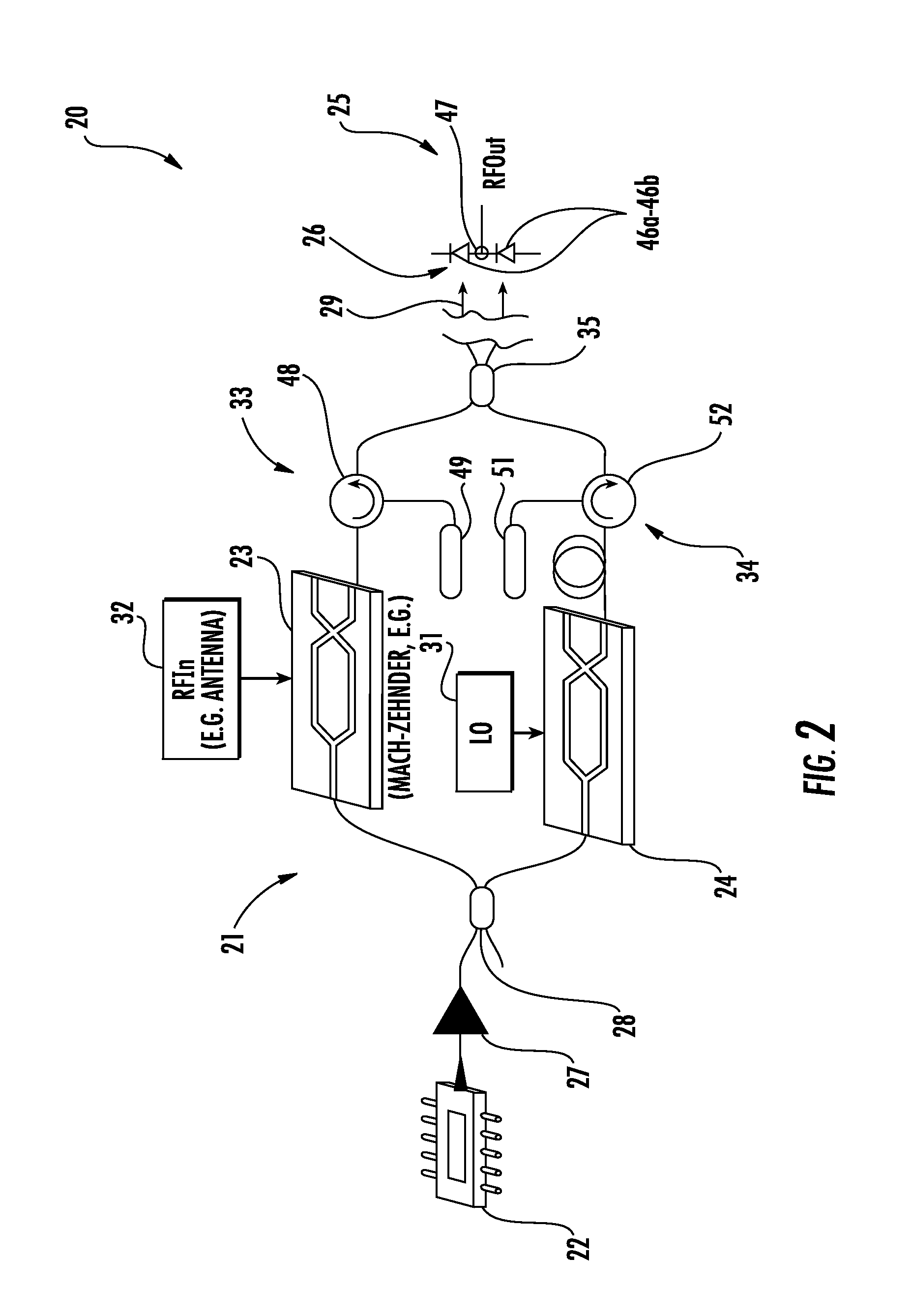
A communications device includes a transmitter device having an optical source configured to generate an optical carrier signal, a first E/O modulator coupled to the optical source and configured to modulate the optical carrier signal with an input signal having a first frequency, and a second E/O modulator coupled to the optical source and configured to modulate the optical carrier signal with a reference signal. The communications device includes an optical waveguide coupled to the transmitter device, and a receiver device coupled to the optical waveguide and including an O/E converter coupled to the optical waveguide and configured to generate an output signal comprising a replica of the input signal at a second frequency based upon the reference signal.

Description

FIELD OF THE INVENTION[0001]The present invention relates to the field of communications, and, more particularly, to radio frequency (RF) communications and related methods.BACKGROUND OF THE INVENTION[0002]A typical wireless communication system comprises a plurality of wireless communications devices exchanging data with each other. In some wireless communication systems, for example, infrastructure networks, the system may further comprise a wireless base station for managing communications between the wireless communications devices. In other words, each intra-system communication would be exchanged via the wireless base station. In other wireless communication systems, for example, mesh networks and ad hoc wireless networks, the wireless base station may be omitted, i.e. the wireless communications devices may communicate directly with each other.[0003]A typical Extremely High Frequency (EHF), i.e. 30 to 300 GHz, communication system operating at this band may have some drawback...

Claims


Application Information

Patent Timeline
IPC IPC(8): H04B10/14
CPCH04B10/00H04B2210/006
Inventor MIDDLETON, CHARLESDESALVO, RICHARDSCHEUTER, PETER S.
Owner HARRIS CORP
Why Eureka
Try Eureka