Honeycomb structure and honeycomb catalyst

a honeycomb catalyst and honeycomb technology, applied in the direction of catalyst activation/preparation, physical/chemical process catalysts, catalyst activation/preparation, etc., can solve the problems of increasing the thermal expansion ratio of the obtained honeycomb catalyst, the purification efficiency of the exhaust gas is worse, and the catalyst does not effectively act. , to achieve the effect of good purification efficiency, good purification efficiency and good thermal expansion ratio

Active Publication Date: 2013-09-12
NGK INSULATORS LTD
View PDF2 Cites 11 Cited by
  • Summary
  • Abstract
  • Description
  • Claims
  • Application Information

AI Technical Summary

Benefits of technology

[0017]In a honeycomb structure of the present invention, partition walls contain “macro pores having the largest pore diameter of larger than 10 μm”. Therefore, a large amount of catalyst can be loaded. Moreover, in the honeycomb structure of the present invention, “a porosity of the partition walls is from 45 to 70%”, and a total area of “the macro pores “having the largest pore diameter of larger than 10 μm”” is 50% or more with respect to a total area of pores. Therefore, when the catalyst is loaded, it is possible to obtain a honeycomb catalyst having a large contact area between the catalyst and an exhaust gas and having a good purification efficiency. That is, the honeycomb structure of the present invention can be used as a support of the honeycomb catalyst having a good purification efficiency. In addition, in the honeycomb structure of the present invention, since “the porosity of the partition walls is from 45 to 70%” and the total area of “the macro pores” is 50% or more with respect to the total area of the pores, the pores closed with the catalyst decrease when the catalyst is loaded. When the pores closed with the catalyst decrease in this way, a thermal expansion ratio of the obtained honeycomb catalyst does not become excessively high as compared with a case where the pores closed with the catalyst is large. Thus, a honeycomb catalyst using the honeycomb structure of the present invention as the support can show an excellent thermal shock resistance.
[0018]A honeycomb catalyst of the present invention includes a honeycomb structure of the present invention, and a catalyst loaded onto the surfaces of the pores being contained in the partition walls, in addition to the surfaces of partition walls, of the honeycomb structure of the present invention. Moreover, in the honeycomb catalyst of the present invention, “a total area of high cavity ratio pores is from 15 to 40% with respect to a total area of the pores”. Therefore, in the honeycomb catalyst of the present invention, one may ensure the formation of through channels capable of providing a good diffusion for the exhaust gas flowing into the honeycomb catalyst. So, the exhaust gas having flowed into the honeycomb catalyst suitably diffuses in the honeycomb catalyst. As a result, a contact chance between the exhaust gas and the catalyst increases. That is, the catalyst is effectively used for purifying the exhaust gas. Accordingly, the honeycomb catalyst of the present invention has a good purification efficiency.

Problems solved by technology

Therefore, the catalyst which does not effectively act increases.
As a result, there has been a problem that the purification efficiency of the exhaust gas becomes worse.

Method used


Image

  • Honeycomb structure and honeycomb catalyst
  • Honeycomb structure and honeycomb catalyst
  • Honeycomb structure and honeycomb catalyst

Examples


example 1

Preparation of Honeycomb Structure

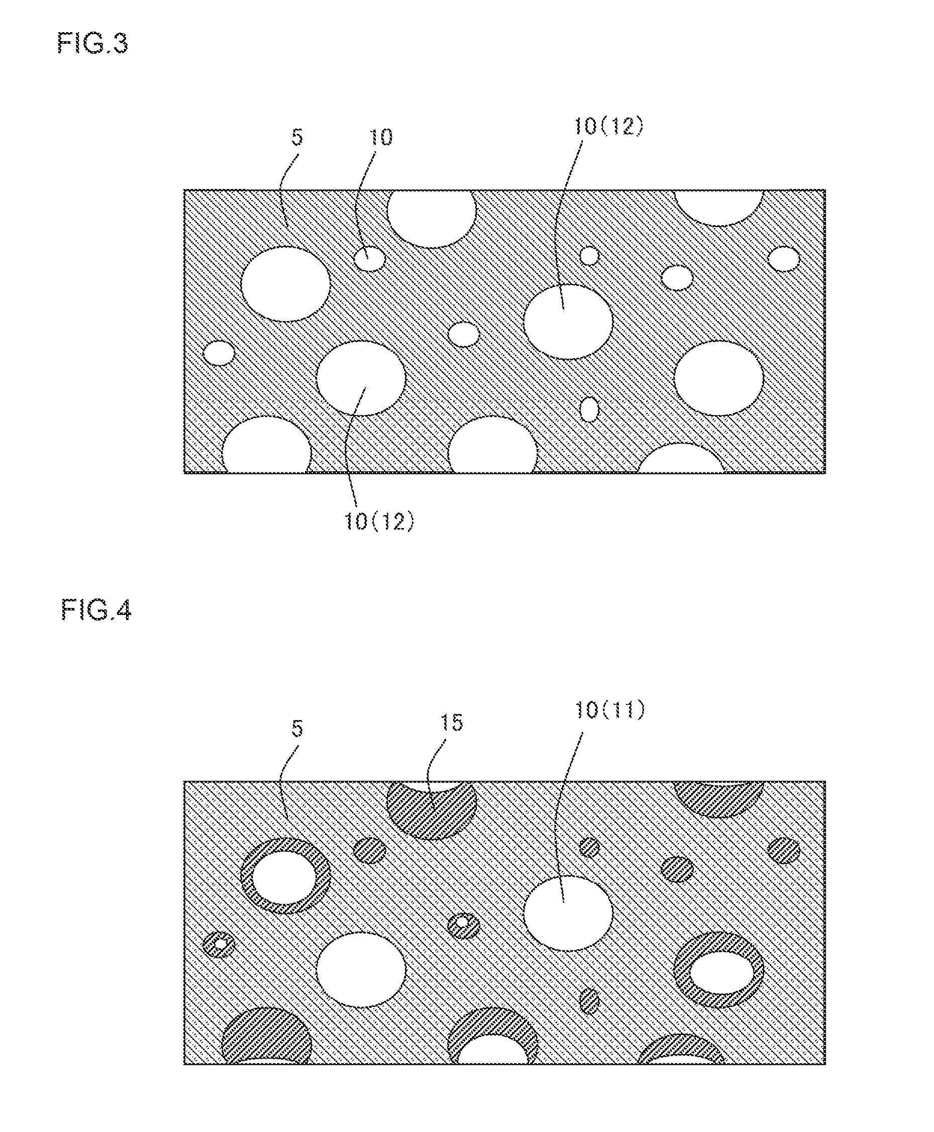
[0088]As a cordierite forming raw material, alumina, aluminum hydroxide, kaolin, talc and silica were used. To 100 parts by mass of the cordierite forming raw material, 17 parts by mass of a pore former, 85 parts by mass of a dispersion medium, 8 parts by mass of an organic binder and 3 parts by mass of a surfactant were added, respectively. Afterward, the materials were mixed and kneaded to prepare a kneaded clay. As the dispersion medium, water was used, and as the pore former, resin balloon having an average particle diameter of 102 μm was used. As the organic binder, hydroxypropyl methylcellulose was used. As a dispersant, ethylene glycol was used.

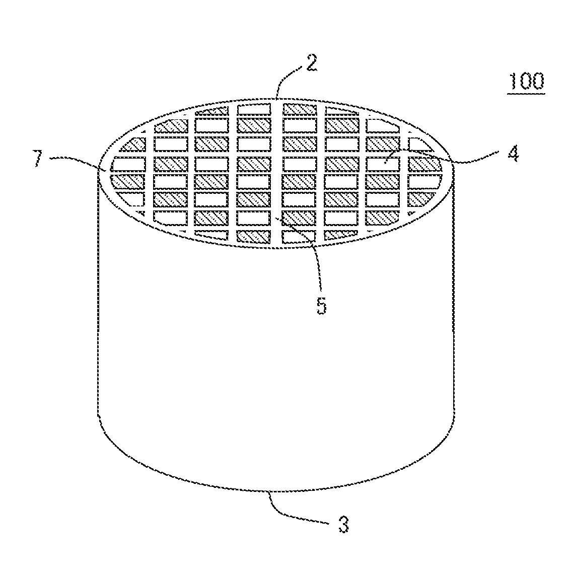
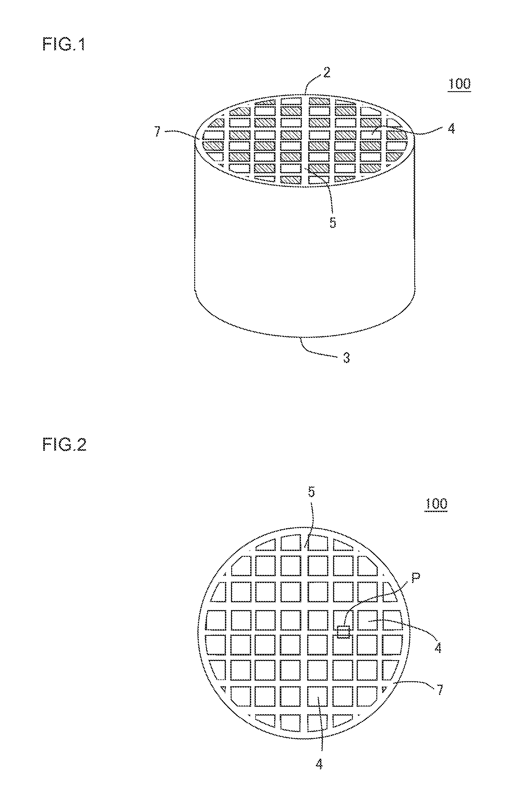
[0089]Next, the kneaded clay was extruded by using a predetermined die to obtain a honeycomb formed body. In cross sections of the honeycomb formed body which were perpendicular to a cell extending direction, quadrangular cells were formed, and the whole shape was a columnar shape. Then, the obtained h...


PUM

PropertyMeasurementUnit
porosityaaaaaaaaaa
pore diameteraaaaaaaaaa
porosityaaaaaaaaaa

Abstract

There is disclosed a honeycomb structure usable as a support of a honeycomb catalyst onto which a large amount of catalyst can be loaded and which has a good purification efficiency, and the honeycomb structure includes porous partition walls 5 defining a plurality of cells to form through channels of a fluid and having a plurality of pores 10 therein, wherein a porosity of the partition walls 5 is from 45 to 70%, and in a cross section perpendicular to an extending direction of the cells, a total area of macro pores 12 having the largest pore diameter of larger than 10 μm is 50% or more with respect to a total area of the pores 10.

Description

[0001]The present application is an application based on JP-2012-049684 filed on Mar. 6, 2012 with the Japanese Patent Office, the entire contents of which are incorporated herein by reference.BACKGROUND OF THE INVENTION[0002]1. Field of the Invention[0003]The present invention relates to a honeycomb structure and a honeycomb catalyst. More particularly, it relates to a honeycomb structure usable as a support of a honeycomb catalyst onto which a large amount of catalyst can be loaded and having a good purification efficiency and showing an excellent thermal shock resistance, and the honeycomb catalyst.[0004]2. Related Art[0005]Heretofore, there has been suggested an exhaust gas purifying device in which a catalyst for purification is loaded onto a catalyst support in order to purify the components to be purified such as nitrogen oxides (NOx) included in an exhaust gas discharged from a stationary engine for a car, a construction machine or an industrial purpose, a burning appliance ...

Claims


Application Information

Patent Timeline
Patent Type & Authority Applications(United States)
IPC IPC(8): B01J35/04
CPCB01J29/7007B01J35/002B01J35/04B01J35/10Y10T428/24149B01J35/1028B01J35/1076B01J37/0018B01J37/0215B01J35/1023
Inventor HIROSE, SHOGOMIYAIRI, YUKIO
Owner NGK INSULATORS LTD
Why Eureka
Try Eureka