
Sliding liquid level sensor

a liquid level sensor and sliding technology, applied in liquid/fluent solid measurement, instruments, machines/engines, etc., can solve the problems of reducing detection accuracy, affecting the detection accuracy, and corroding silver, so as to reduce the amount of glass added to the electrodes, reduce the amount of silver sulfide, and reduce the formation of silver sulfid

Active Publication Date: 2013-09-19
AISAN IND CO LTD +1
View PDF3 Cites 6 Cited by
  • Summary
  • Abstract
  • Description
  • Claims
  • Application Information

AI Technical Summary

Benefits of technology

This patent discusses a new design for liquid level sensors that reduces abrasion and wear between the electrodes and the sliding contact point. This is achieved by using electrodes with less silver, which decreases the formation of silver sulfide and maintains good conductivity. Additionally, the electrodes contain a predetermined amount of silver to ensure proper conductivity. The electrodes also have a proper amount of glass to prevent excessive hardness and reduce abrasion. The sliding contact point is made with materials that are less susceptible to oxidation or sulfurization, such as palladium or nickel, which reduces manufacturing costs. Overall, this design improves efficiency and durability of liquid level sensors.

Problems solved by technology

Silver, however, can get corroded through contact with a liquid fuel component such as those containing sulfur, water or alcohol.
Such deterioration or corrosion can cause the connection to become loose.
Since silver sulfide is an insulator, the silver sulfide membrane causes a loose connection, resulting in an eventual decrease in detection accuracy.
However, since the electrodes contain silver as a major component, it is not able to effectively prevent silver sulfide formation.
In addition, the large amount of glass makes the electrodes too hard, so that it is necessary to harden the contact point in accordance with the hardness of the electrodes.
However, copper, like silver is easily sulfurized or oxidized when coming in contact with a liquid fuel.

Method used


Image

  • Sliding liquid level sensor
  • Sliding liquid level sensor
  • Sliding liquid level sensor

Examples


example 1

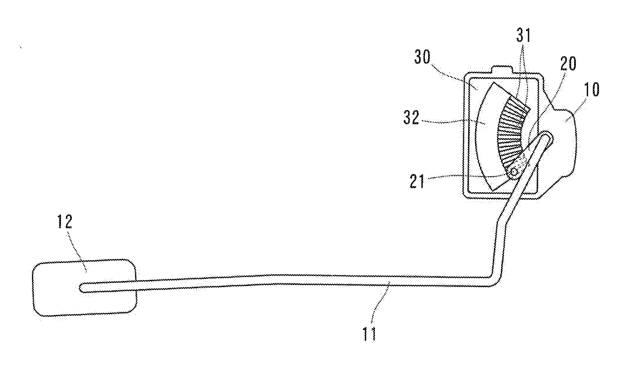
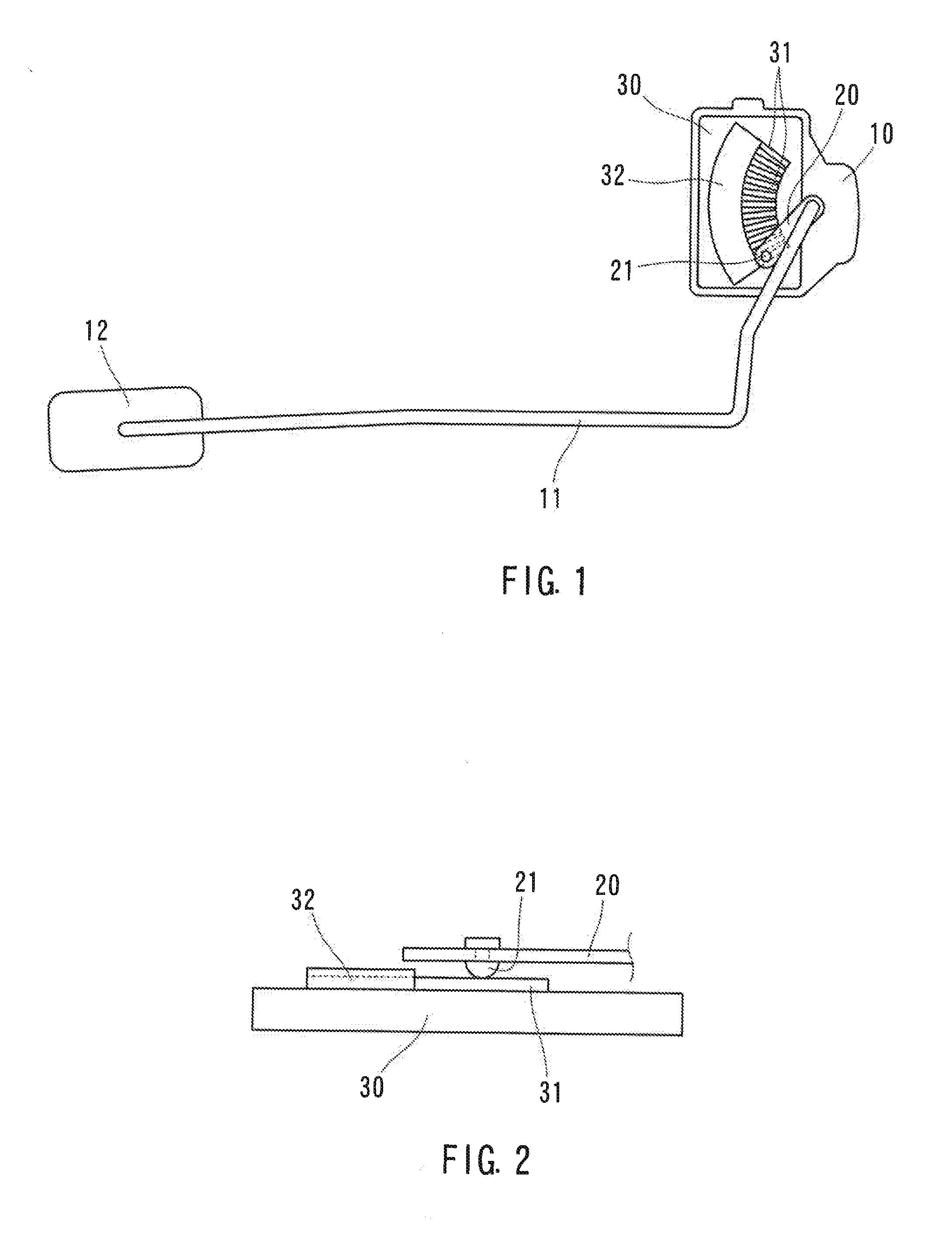
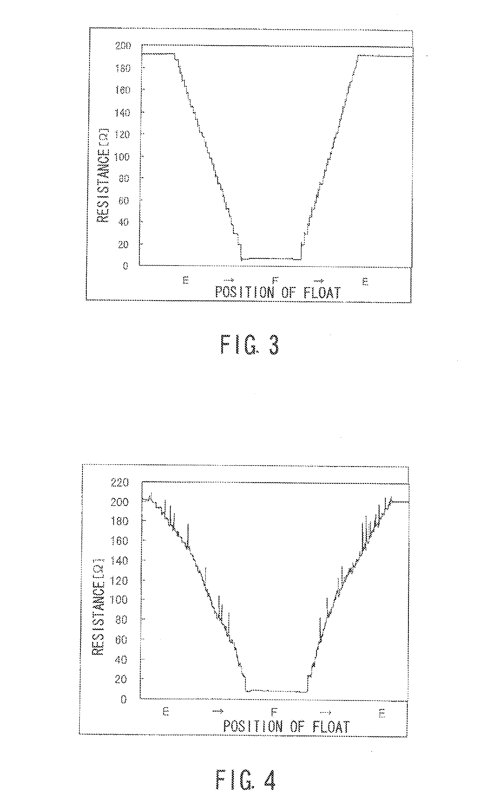
[0025]A plurality of electrodes each formed in a strip shape were printed on an alumina plate by a screen printing method, and then were dried and heated. The heating step was carried out at 850° C. for 10 min. The electrodes contained 25% by weight of silver and 75% by weight of palladium and further contained 3.4 parts by weight of glass per 100 parts of combination of silver and palladium. Each of the electrodes was shaped such that its width was about 0.2 mm and its length was about 5 mm, and about 50 electrodes were radially arranged in an arc-shape. Then, a resistor mainly containing ruthenium oxide and glass was formed in a band shape contacting with outer ends of the electrodes through a printing step and a heating step. In addition, a sliding contact point containing 80% by weight of palladium and 20% by weight of nickel was formed to have the thickness of 0.2 mm and was attached to a base made from copper nickel by welding such that the sliding contact point was positioned...


PUM


Abstract

Embodiments of the invention are directed towards a sliding liquid level sensor which is mounted in a fuel tank of a vehicle for detecting a remaining amount of a liquid fuel in the tank. The liquid level sensor has a float, a plurality of electrodes, and a sliding contact point configured to slide on the electrodes in accordance with a displacement of the float. The electrodes preferably contain 100 parts by weight of a silver-palladium alloy and preferably 3-20 parts by weight of glass. The silver-palladium alloy preferably contains 20-60% by weight of silver and preferably 80-40% by weight of palladium. The sliding contact point is made from a palladium-nickel alloy that preferably contains 70-90% by weight of palladium and preferably 30-10% by weight of nickel.

Description

[0001]This application claims priority to Japanese patent application serial number 2012-057325, the contents of which are incorporated herein by reference.BACKGROUND OF THE INVENTION[0002]This disclosure relates to a liquid level sensor for detecting a remaining amount of a liquid fuel in a fuel tank mounted on a vehicle. In particular, it relates to a sliding liquid level sensor having a contact point sliding over a plurality of electrodes in accordance with the movement of a float.[0003]In conventional sliding liquid level sensors, silver often serves as major component in alloys, such as silver-palladium alloy or silver-nickel alloy. They are typically used for a sliding contact point and electrodes. Silver has low electrical resistance and thus has good conductivity. Silver, however, can get corroded through contact with a liquid fuel component such as those containing sulfur, water or alcohol. Such deterioration or corrosion can cause the connection to become loose. In particu...

Claims


Application Information

Patent Timeline
IPC IPC(8): G01F23/60
CPCG01F23/363G01F23/60B60K15/00G01F23/36H01C10/00
Inventor TAKAGI, KUNIOJANG, JIN WOOKKWAK, HOON PYO
Owner AISAN IND CO LTD
Learn More