
Engine and engine power tool

Active Publication Date: 2013-09-19
HITACHI KOKI CO LTD
View PDF14 Cites 4 Cited by
  • Summary
  • Abstract
  • Description
  • Claims
  • Application Information

AI Technical Summary

Benefits of technology

The present invention aims to improve the cooling effect of the engine. A cooling fan is provided at the end of the crankshaft to generate a cooling wind towards the cylinder, and a heat-dissipating plate is placed at the opposite end to enhance the heat-dissipating effect. This structure prevents heat transmission to the handle and even in natural cooling after engine stop. The heat-dissipating plate extends along the cylinder from one end to the other, guiding the cooling wind and enhancing the forcible cooling effect.

Problems solved by technology

Therefore, the temperature difference from the air is small, natural convection generated at the heat-dissipating fin becomes weak, and the heat-dissipating effect caused by natural air cooling cannot be sufficiently exerted.
Moreover, a thin member having a high thermal conductivity is used as the heat-dissipating fin interposed between the vaporizer and the insulator, and the effect of sufficiently reducing the temperature increase of the vaporizer cannot be obtained also from the point that the heat of the insulator is immediately thermally conducted to the vaporizer.
However, such a problem cannot be solved by conventional engines.

Method used


Image

  • Engine and engine power tool
  • Engine and engine power tool
  • Engine and engine power tool

Examples


Embodiment Construction

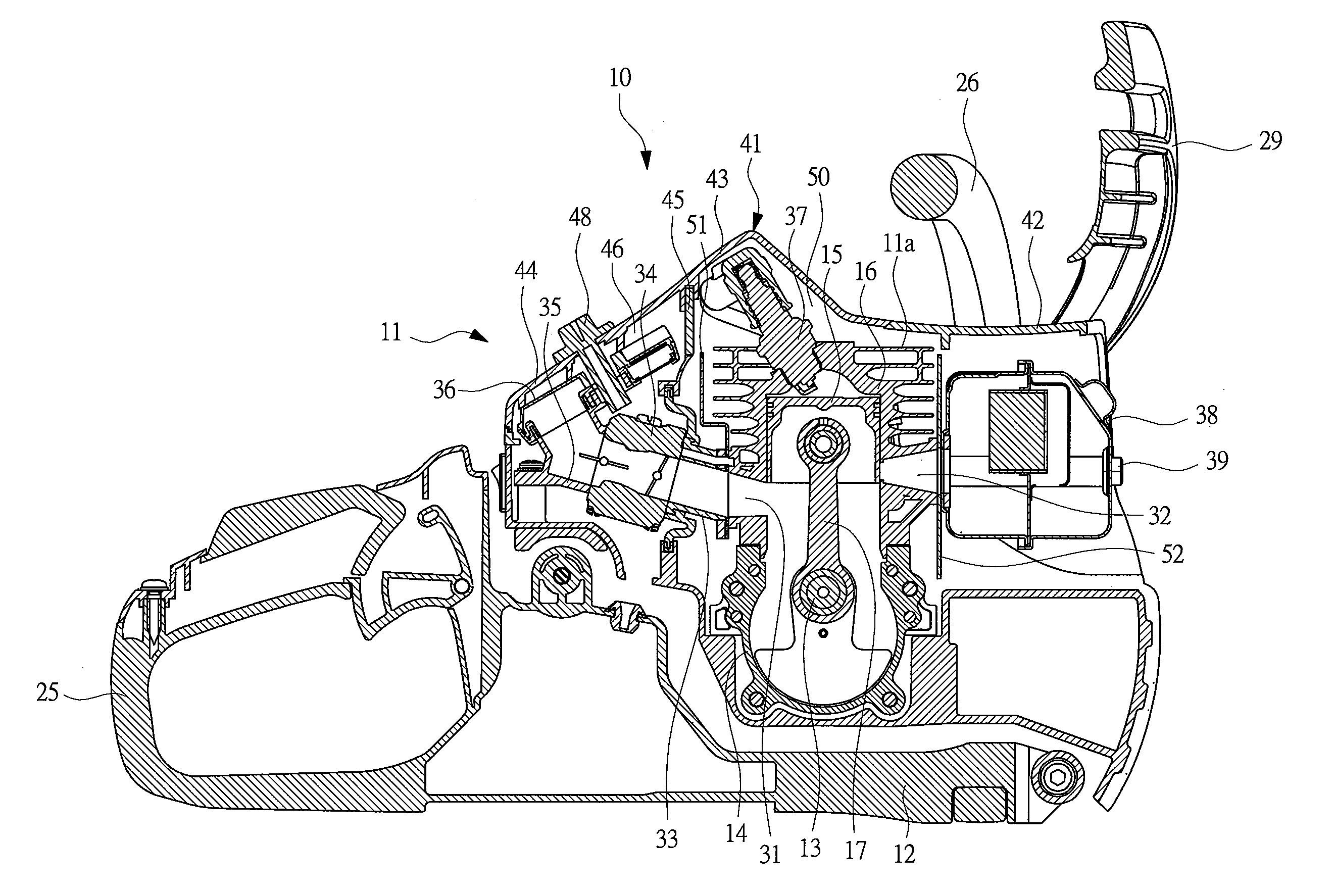
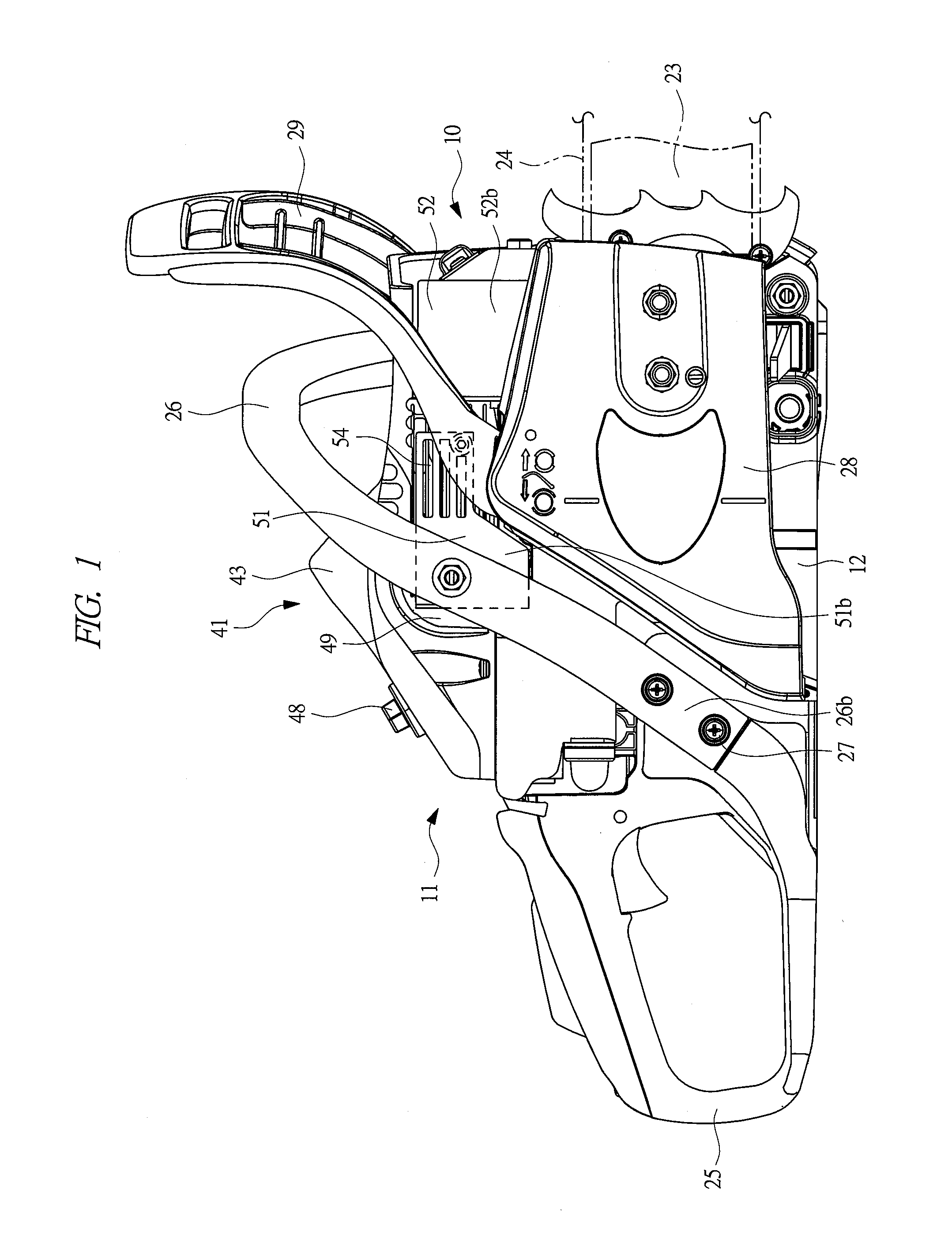
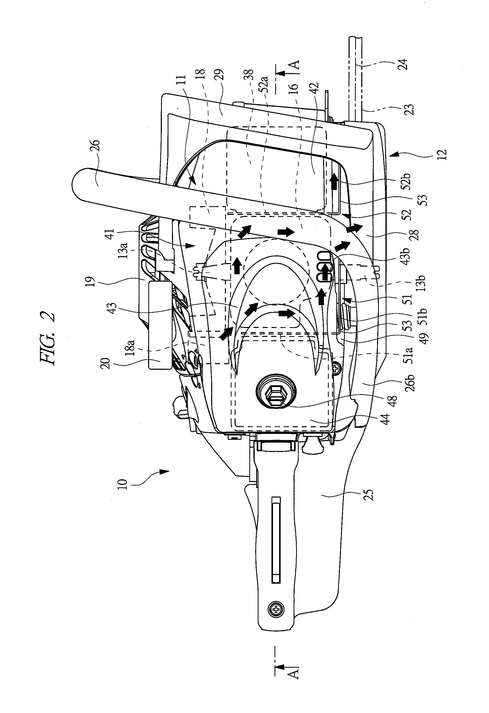
[0018]Hereinafter, an embodiment of the present invention will be explained in detail based on the attached drawings. A chain saw 10 serving as an engine power tool has a power-tool main body 12, in which an engine 11 is built, as shown in FIG. 2. The engine 11 has an engine main body 11a including a crankcase 14 that includes a drive shaft, i.e., a crankshaft 13 rotatably built in, and a cylinder 16 that includes a piston 15 linearly and reciprocatably built in. Each of the crankcase 14 and the cylinder 16 is formed of an aluminum alloy. The piston 15 is coupled to the crankshaft 13 by a connecting rod 17, and the reciprocating motion of the piston 15 is converted to the rotating motion of the crankshaft 13.

[0019]As illustrated in FIG. 2, a cooling fan 18 is attached to a first projecting end 13a of a crankshaft 13, the cooling fan 18 is housed in a not-illustrated volute case attached to the power-tool main body 12, and a fan cover 19 is attached to the power-tool main body 12 so ...


PUM


Abstract

The cooling effect of an engine is improved. An engine, which rotationally drives a saw chain serving as a rotating tool, is provided with a crankcase, in which a crankshaft is rotatably built, and a cylinder, in which a piston coupled to the crankshaft via a connecting rod is reciprocatably built. Atop part of the cylinder is covered with a cylinder cover, and a cooling wind toward the cylinder is generated by a cooling fan attached to a projecting end of the crankshaft. The cooling wind is guided by heat-dissipating plates extending along the crankshaft. Exposing parts bulged to outside than a lateral side of the cylinder cover are provided to tips of the heat-dissipating plates.

Description

CROSS-REFERENCE TO RELATED APPLICATION[0001]The present application claims priority from Japanese Patent Application No. 2012-058234 filed on Mar. 15, 2012, the content of which is hereby incorporated by reference into this application.TECHNICAL FIELD OF THE INVENTION[0002]The present invention relates to an engine mounted on a portable type engine power tool such as a chain saw or a power cutter and to the engine power tool.BACKGROUND OF THE INVENTION[0003]Examples of a hand-held type or a portable type engine power tool using an engine as a drive source include a chain saw and a power cutter. In the chain saw, a saw chain, which is a chain-shaped saw blade for cutting a working object such as timber is provided in a power-tool main body. In the power cutter, a disk cutter for groove-forming or cutting of stone materials or concrete is provided in a power-tool main body. An engine mounted on such an engine power tool has an engine main body including a crankcase, to which a cranksh...

Claims


Application Information

Patent Timeline
IPC IPC(8): F01P1/00
CPCF01P1/00F01P9/00F01P1/02
Inventor ICHIHASHI, NAOTO
Owner HITACHI KOKI CO LTD
Learn More