Method for producing metal composite, and chassis for electronic equipment

a metal composite and electronic equipment technology, applied in the direction of casings/cabinets/drawers, instruments, casings/cabinets/drawers details, etc., can solve the problems of low composite production efficiency, difficult to ensure the required bonding strength, flaking of metal composites, etc., to achieve excellent amenability to thin-walling, high degree of design freedom, and high degree of rigidity.

Active Publication Date: 2013-09-19
TORAY IND INC
View PDF6 Cites 52 Cited by
  • Summary
  • Abstract
  • Description
  • Claims
  • Application Information

AI Technical Summary

Benefits of technology

[0019]The task of the present invention is to provide manufacturing methods for metal composites which integrate metal materials together or metal materials and other structural materials via a cured resin layer or layers, which easily achieve an ability to process high-rigidity metal materials with an excellent amenability to thin-walling and lightweighting and a high degree of design freedom into complex shapes and an ability for fast compositing as demanded by the market, and which are able to produce metal composites having excellent bonding strength, as well as electronic equipment chassis that use metal composites obtained through such manufacturing methods.
[0029]a step 3 for cooling down the metal composite molded in the step 2 under pressure so as to lower the surface temperature of the metal material to 180° C. or less.
[0061]The present invention provides manufacturing methods for metal composites which integrate metal materials together or metal materials and other structural materials via a cured resin layer or layers, which easily achieve an ability to process high-rigidity metal materials having an excellent amenability to thin-walling and lightweighting and a high degree of design freedom into complex shapes and an ability for fast compositing as demanded by the market, and which are able to produce metal composites having excellent bonding strength, as well as electronic equipment chassis that use metal composites obtained through such manufacturing methods. It also provides electronic equipment chassis incorporating an electromagnetic shielding capability and antenna characteristics as required of electronic equipment fitted with telecommunications features.

Problems solved by technology

However, such a manufacturing method is problematic in that it separately requires a metal material molding step and a molding step for whatever other structural material to be composted with the metal material, resulting in a low composite production efficiency.
Furthermore, since a thermosetting resin is introduced after a metal material has been molded into a complex shape, it is difficult to guarantee that the required bonding strength is provided in the manufacturing process, and, for this reason, there is a risk that, if, for instance, a thermosetting resin is not adequately placed, even if only in parts, problems such as the flaking of the metal composites arise during use.
Furthermore, since such electronic equipment chassis require a resin layer aimed at providing bonding, there is deficiency in the amenability to thin-wall design and degree of design freedom, and this has given rise to the problem of undermining the ongoing efforts to reduce the weight of electronic equipment.
There is another problem in that, since separate processing steps are required for the metal material and fiber-reinforced resin, the production cost of chassis is high due to a need for a large amount of production equipment needed.

Method used


Image

  • Method for producing metal composite, and chassis for electronic equipment
  • Method for producing metal composite, and chassis for electronic equipment
  • Method for producing metal composite, and chassis for electronic equipment

Examples


example 1-(

13)

[0242]The same setup as Example 1-(9) was used, except that industrial pure titanium plates (KS40) were adopted as metal materials. The manufacturing conditions and evaluation results for Example 1-(13) are shown in Table 9 and Table 10.

Comparative Example 1-(1)

Preparation of Preform

[0243]Using the same method as Example 1-(1), except that the thermosetting resin was mixed at the composition mass ratio shown in Table 11, a metal composite was produced.

[0244]Here, using press molding equipment, the sheet substrate was mounted on a plate with a surface temperature of 130° C. and simultaneously heated and compressed at 1 MPa for 10 minutes. The glass transition temperature (Tg) of the resin in the obtained metal composite was measured and found to be 75° C. Since this glass transition temperature (Tg) was 52% of the saturated glass transition temperature (Tg), the resin was confirmed to be in a semi-cured state.

[0245]Production of Metal Composite:

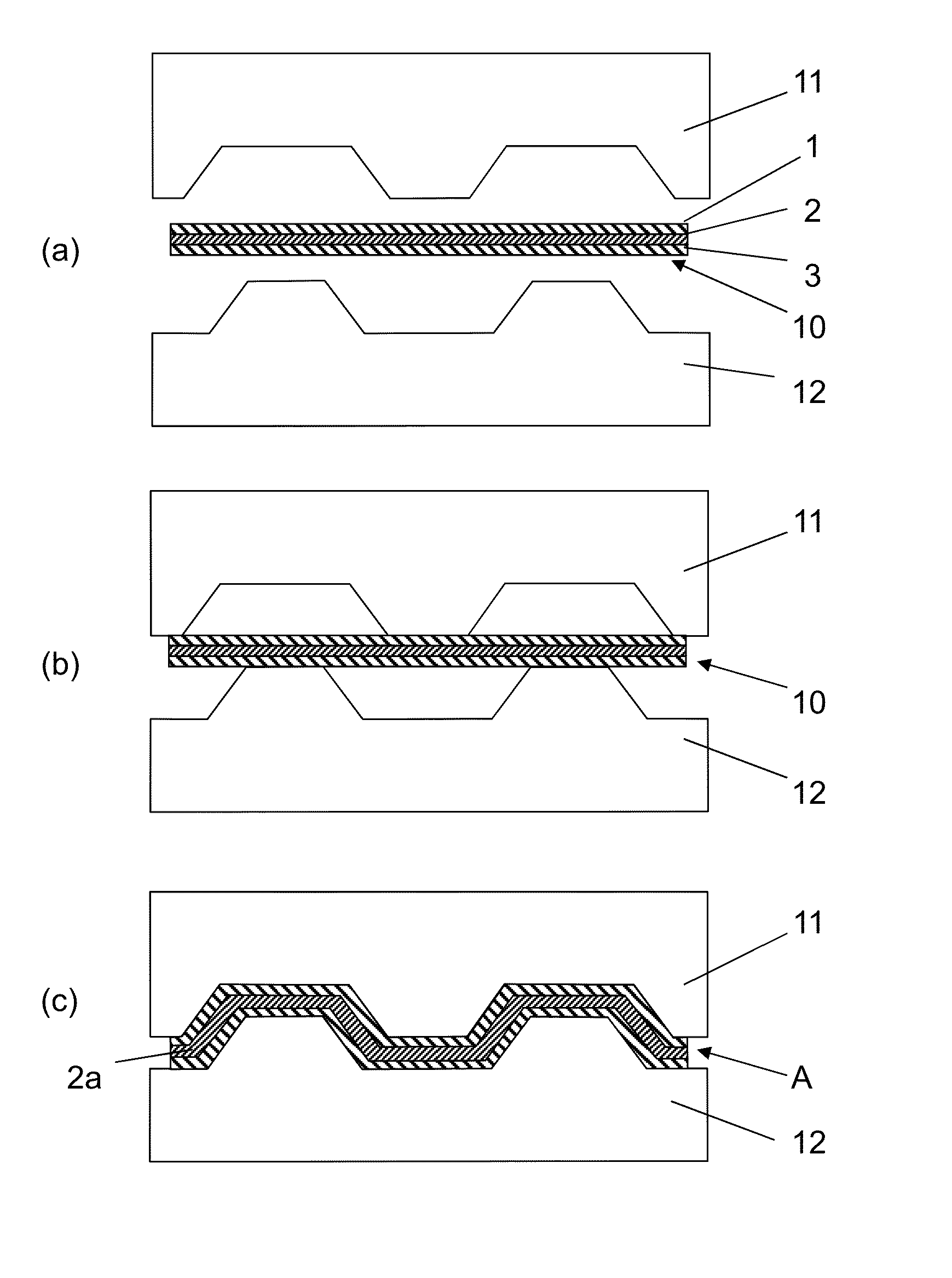
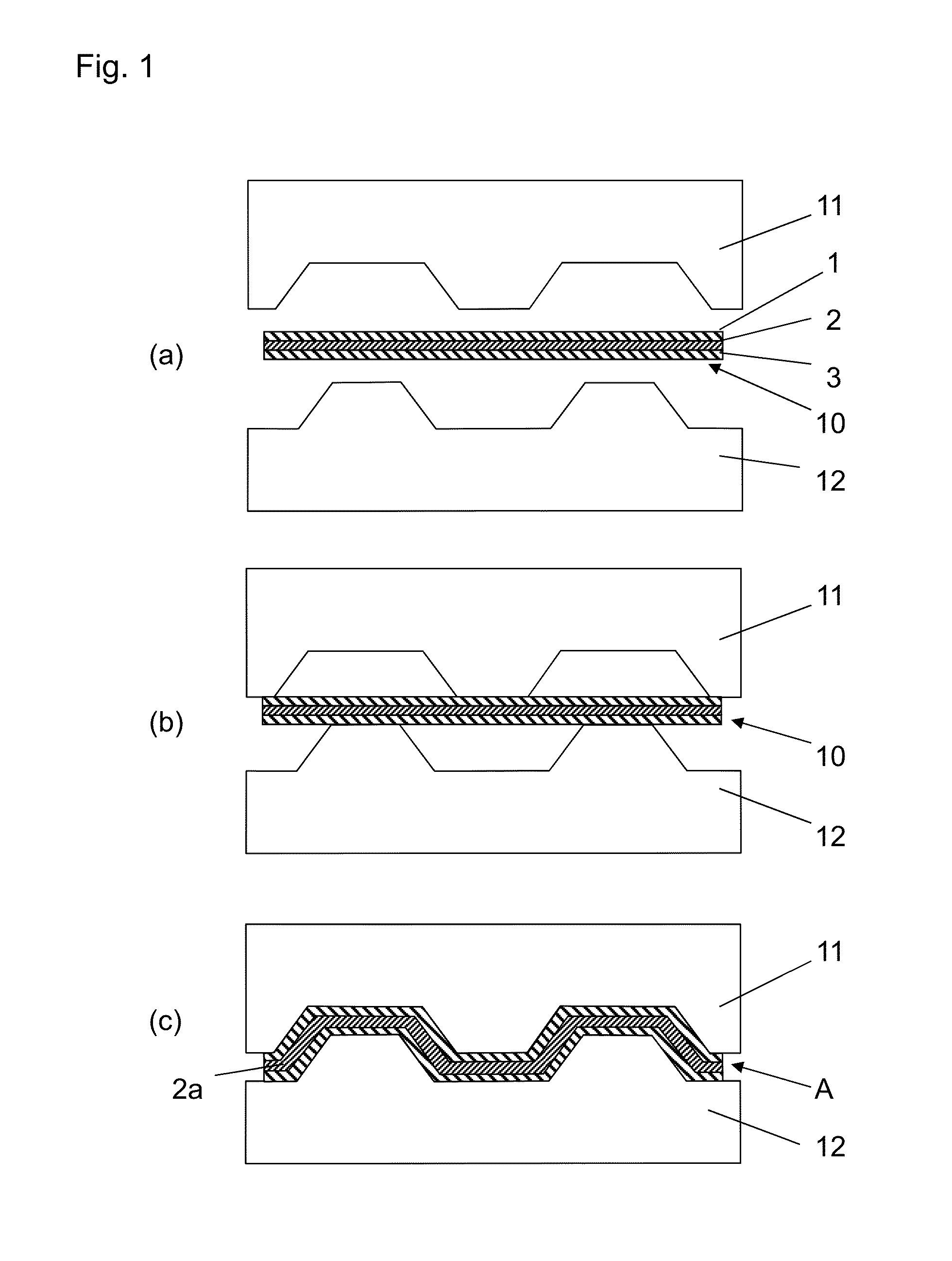
[0246]As illustrated in FIG. 1 (b), ...

example 2-(

6)

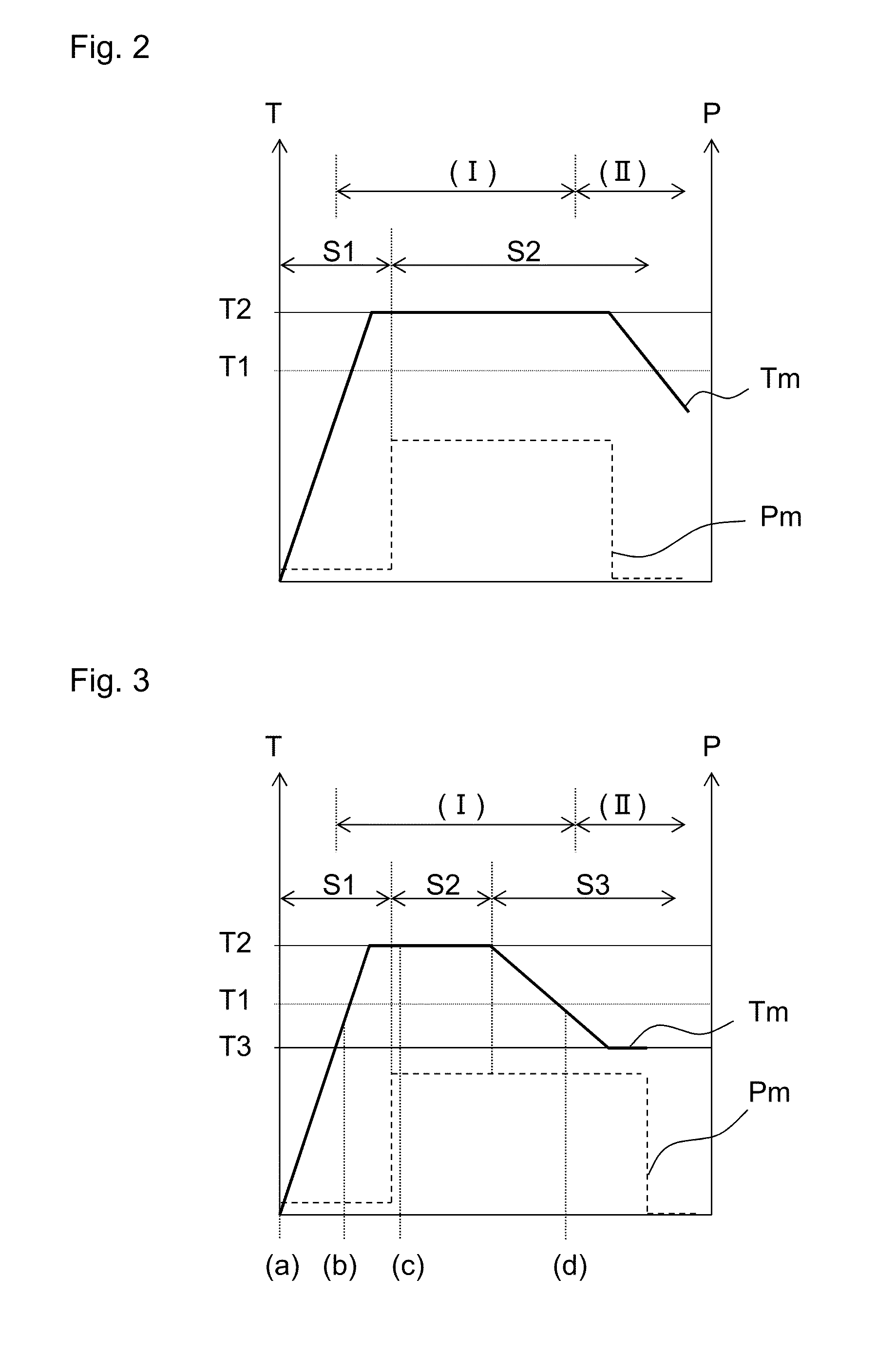
[0281]The same preform as the Example 2-(1) was used. About 30 seconds after heating in the step 1 began, compression in the step 2 was started, and about 30 seconds later, cooling water was passed through the upper mold and the lower mold as the step 3 to cool them to 180° C. or less, with their temperature setting changed to 170° C. About 2 minutes after cooling began, the surface temperature of the metal material fell to 180° C. or less, and compression was applied for about 1 minute thereafter. After this, the mold was opened, and the metal composite was taken out of it, followed by 10 minutes post curing performed by placing the metal composite into a hot air furnace whose ambient temperature had been adjusted to 150° C. The obtained metal composite was evaluated in the same manner as Example 2-(1). The manufacturing conditions and evaluation results for Example 2-(6) are shown in Table 15 and Table 16.

Comparative Example 2-(1)

Preparation of Preform

[0282]Using the same method...

example 3-(

7)

Preparation of Thermosetting Resin

[0329]The thermosetting resin was prepared as a resin composition under the same conditions as Example 3-(1), except that the composition mass ratio was changed to the one shown in Table 23.

[0330]The prepared resin composition was subjected to a glass transition temperature (Tg) measurement using the same measurement method as Example 3-(1). The glass transition temperature (Tg) of the resin composition was 6° C., while the saturated glass transition temperature (Tg), which had been reached through curing, was 136° C. It can be said that, when the glass transition temperature (Tg) is in the 13 to 117° C. range, the resin composition is in a semi-cured state.

[0331]The relationship between the heating temperature, heating duration and glass transition temperature (Tg) of the prepared resin composition was examined in the same manner as Example 3-(1). With the heating temperature fixed at 130° C. and 150° C., the glass transition temperature (Tg) was...


PUM

PropertyMeasurementUnit
temperatureaaaaaaaaaa
surface temperatureaaaaaaaaaa

Abstract

A method is provided for producing a metal composite. The composite includes a metal material and a resin curing layer provided along the metal material, and is obtained by using heat and pressure to mold a preform. The preform includes a sheet-shaped base material containing a thermosetting resin, and a metal material arranged or layered so as to contact the sheet-shaped base material. The method for producing a metal composite includes heating the sheet-shaped base material and semi-curing the thermosetting resin while the metal material in the preform arranged inside a mold is heated to a temperature exceeding 180° C., and molding the preform into a composite using pressure, wherein the thermosetting resin is at least one type selected from the group consisting of epoxy resins, phenol resins, benzoxazine resins, and unsaturated polyester resins.

Description

CROSS-REFERENCE TO RELATED APPLICATIONS[0001]This application is the U.S. National Phase application of PCT International Application No. PCT / JP2011 / 076999, filed Nov. 24, 2011, and claims priority to Japanese Patent Application No. 2010-269150, filed Dec. 2, 2010; Japanese Patent Application No. 2011-029457, filed Feb. 15, 2011; Japanese Patent Application No. 2011-058929, filed Mar. 17, 2011; and Japanese Patent Application No. 2011-058930, filed Mar. 17, 2011, the disclosures of which are incorporated herein by reference in their entireties for all purposes.FIELD OF THE INVENTION[0002]The present invention relates to a method for producing a metal composite and an electronic equipment chassis using a metal composite produced by the method.BACKGROUND OF THE INVENTION[0003]A metal composite produced by laminating a metal material and a fiber-reinforced resin material and bonding them together combine homogeneous strength and elastic modulus, excellent impact resistance, thermal con...

Claims


Application Information

Patent Timeline
Patent Type & Authority Applications(United States)
IPC IPC(8): B29C70/02H05K7/02
CPCB29C45/14221B29C2045/14286B29C2045/14245B29K2701/10B29K2705/00B32B1/00B32B15/14B32B15/20B32B2250/03B32B2250/40B32B2260/021B32B2260/046B32B2305/076B32B2305/77B32B2457/00H05K9/0084B29C70/46B29C70/885B29C70/088B29C70/021H05K7/02B29C45/14811B29C43/18B29C43/36B29C45/14B29C51/08B32B15/08H05K5/02
Inventor FUJIOKA, TAKASHIHONMA, MASATO
Owner TORAY IND INC
Why Eureka
Try Eureka