
Electrocardiogram signal compression and de-compression system

a compression and decompression system technology, applied in the field of digital signal processing, can solve the problems of high cost of many medical instruments, large amount of memory, and typical medical instruments usually do not have enough memory for processing signals, and achieve excellent compression ratio, low distortion rate, and excellent quality score

Inactive Publication Date: 2013-09-19
NAT CHENG KUNG UNIV
View PDF3 Cites 121 Cited by
  • Summary
  • Abstract
  • Description
  • Claims
  • Application Information

AI Technical Summary

Benefits of technology

The invention is a system that compresses and de-compresses electrocardiogram signals with high compression ratios and low distortion rates. This results in a high quality score after de-compression.

Problems solved by technology

Because the generation of electrocardiogram (ECG) requires continuously recording electrocardiogram signals, typical medical instruments usually do not have enough memory for processing the signals.
The storage of such data requires a great amount of memory, resulting in high cost for many medical instruments.
However, with the advance of the technology, no matter for the flash memory, the dynamic random access memory or the hard disk, the storage capacity has been greatly increased, so that the compression ratio is no longer the major target for ECG compression.

Method used


Image

  • Electrocardiogram signal compression and de-compression system
  • Electrocardiogram signal compression and de-compression system
  • Electrocardiogram signal compression and de-compression system

Examples


Embodiment Construction

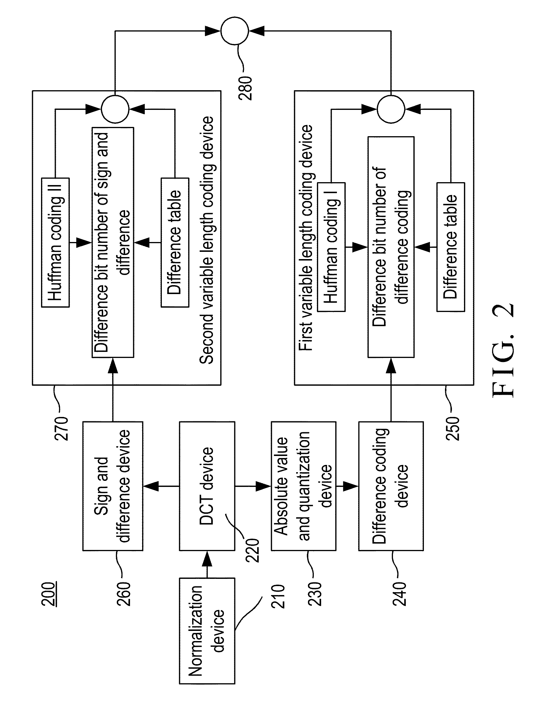
[0044]FIG. 2 is a block diagram showing the electrocardiogram (ECG) signal compression system 200 in accordance with a preferred embodiment of the present invention. The system 200 includes normalization device 210, a discrete cosine transform (DCT) device 220, an absolute value and quantization device 230, a difference coding device 240, a first variable length coding device 250, a sign and difference device 260, a second variable length coding device 270, and a mixer 280.

[0045]There are 64 samples of signals per frame inputted to the ECG signal compression system 200 of the present invention and, after compression, there are 67 compressed bit streams generated for output, each compressed bit stream being composed of Huffman coding and difference table address, wherein three of the compressed bit streams are provided for recording signs and the remaining 64 of the compressed bit streams are the result of the input signals after being transformed and compressed. The data format of t...


PUM


Abstract

The invention provides an electrocardiogram signal compression and de-compression system. The invention uses the sign characteristics of the coefficients of the discrete cosine transform type IV and the characteristics of quantization of spectrum to perform the differential pulse code modulation of the spectrum for preserving the high frequency characteristics of the spectrum of the discrete Fourier transform. The invention also uses the Huffman coding to increase the compression ratio. Different from the conventional compression technology, the invention uses the fact that the quantization values of the spectrum in the high frequency are almost the same to increase the compression ratio and preserve the characteristics of high frequency components of the spectrum.

Description

BACKGROUND OF THE INVENTION[0001]1. Field of the Invention[0002]The present invention relates to the technical field of digital signal processing and, more particularly, to an electrocardiogram signal compression and de-compression system.[0003]2. Description of Related Art[0004]Because the generation of electrocardiogram (ECG) requires continuously recording electrocardiogram signals, typical medical instruments usually do not have enough memory for processing the signals. Taking the existent multi-lead-tapeless ECG Holter system as an example, it uses semiconductor memory as storage media. The semiconductor memory has to store a system program and three ECG signal recordings each for continuous 24 hours. The storage of such data requires a great amount of memory, resulting in high cost for many medical instruments.[0005]Due to the great amount of data and long recording time for ECG, there are lots of ECG signal compressing methods proposed for reducing the cost. As a result, curr...

Claims


Application Information

Patent Timeline
IPC IPC(8): H04L29/08
CPCH04L29/08792G06F19/36H03M7/3059G16H10/40H04L67/565H04L67/5651
Inventor LEI, SHEAU-FANGLAI, SHIN-CHILAN, CHIEN-SHENG
Owner NAT CHENG KUNG UNIV
Learn More