Method of manufacturing an ultrasound transducer and devices including an ultrasound transducer

Active Publication Date: 2013-09-19
OLDELFT
View PDF5 Cites 15 Cited by
  • Summary
  • Abstract
  • Description
  • Claims
  • Application Information

AI Technical Summary

Benefits of technology

[0020]According to a first aspect of the invention, a method for manufacturing an ultrasound transducer for an ultrasound imaging device includes the step of providing an additional layer on the wafer carrier. This additional layer, acting as a buffer layer for dicing, is provided between the wafer carrier and the layer of piezo elements. In a further aspect, there can even be intermediate layers between the buffer layer and the wafer carr

Problems solved by technology

However, when larger probes are used internally, they are uncomfortable and allow less freedom of movement.
These movements of the probe, however, can be very uncomfortable for the patient when used internally.
Disadvantageously, two dimensional array ultrasound transducers are complex.
As these transducer elements are arranged in a two dimensional array, the amount of transducer elements is very large, especially if a certain image resolution is required.
Manufacturing these arrays is thus challenging.
These gaps, however, increase the structural dimensions of the array and make the individual elements less stable as the physical strength of t

Method used


Image

  • Method of manufacturing an ultrasound transducer and devices including an ultrasound transducer
  • Method of manufacturing an ultrasound transducer and devices including an ultrasound transducer
  • Method of manufacturing an ultrasound transducer and devices including an ultrasound transducer

Examples


Example

[0045]Like parts are shown with the same reference numerals.

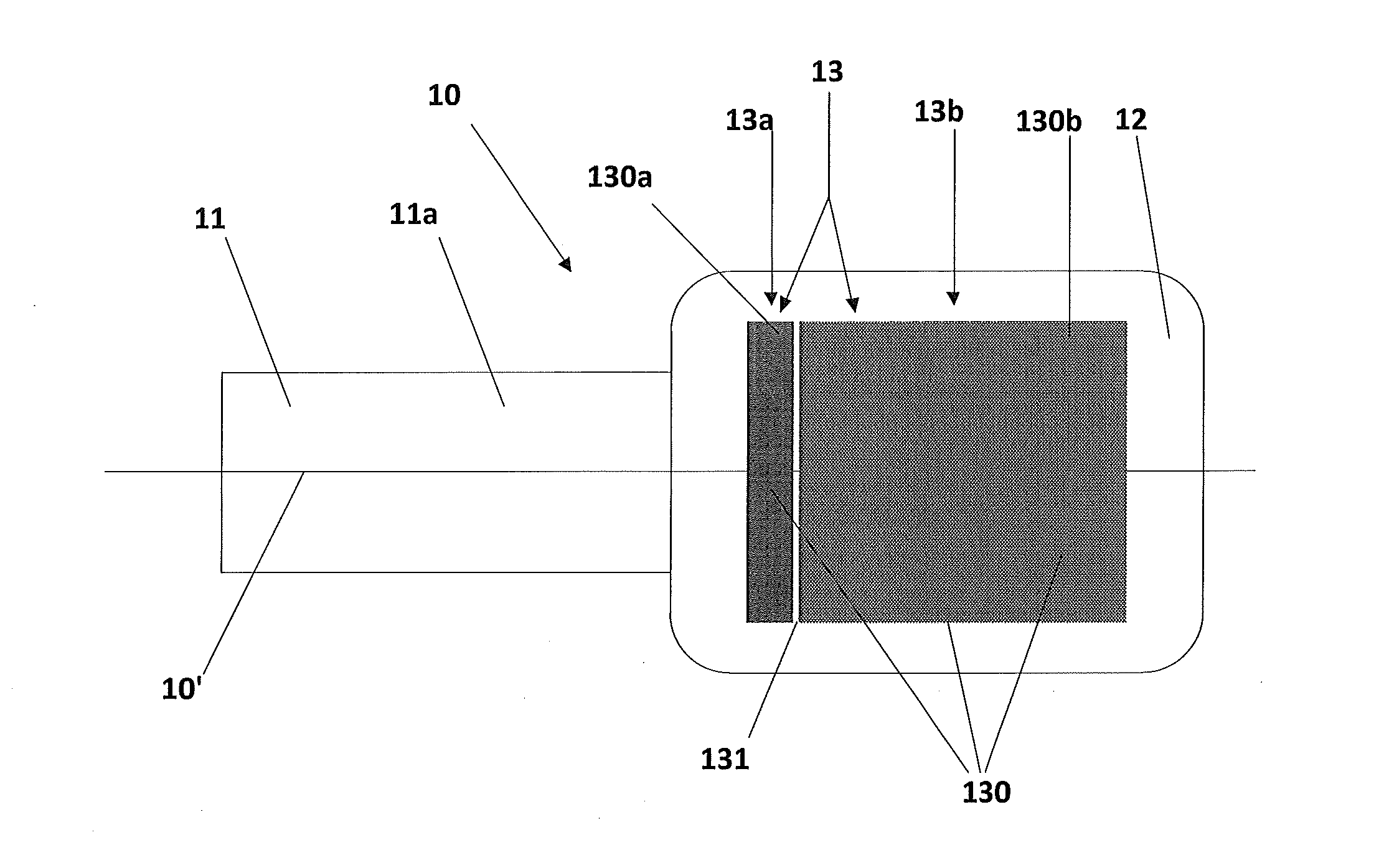
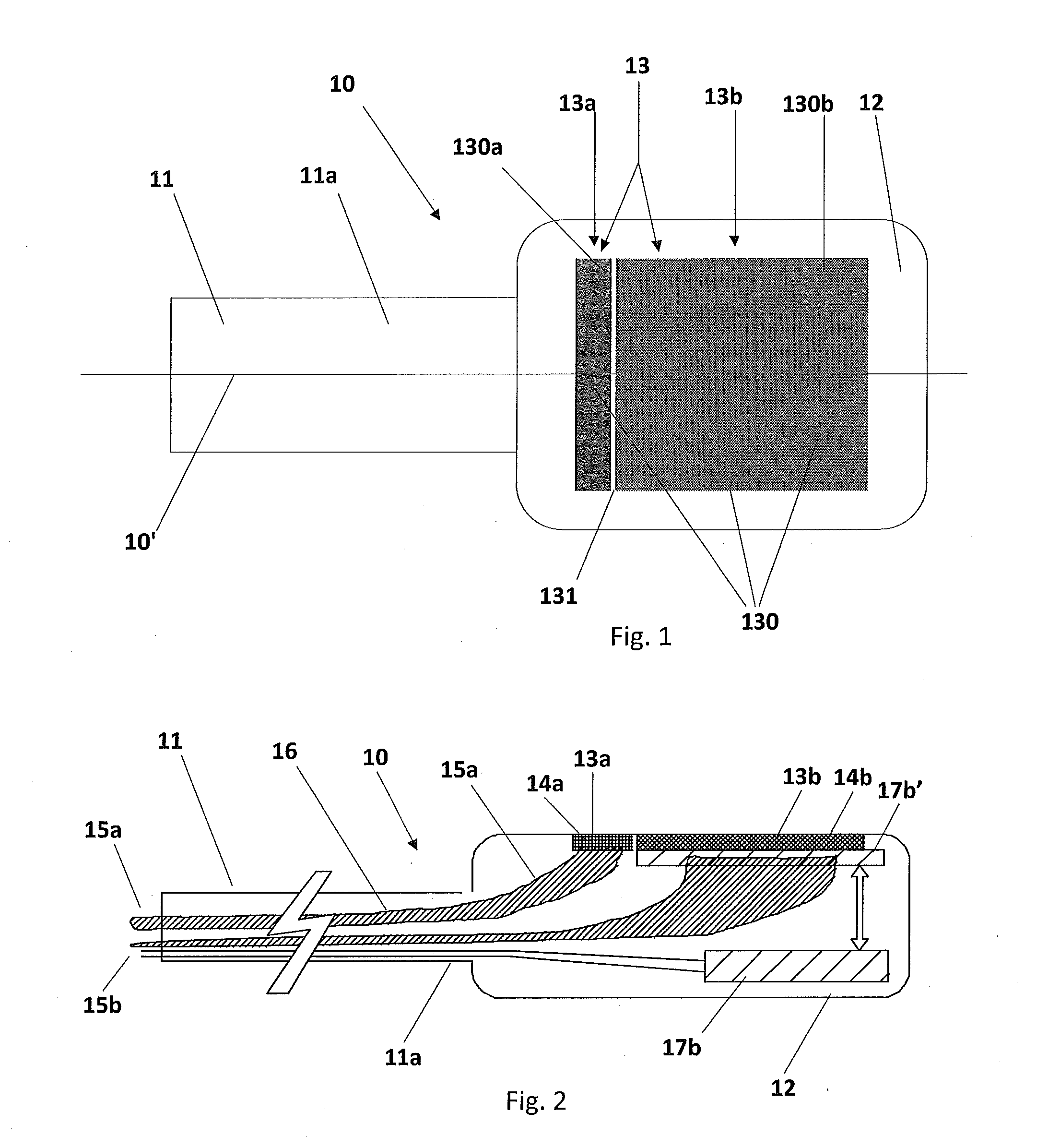
[0046]FIG. 1 illustrates an example of an ultrasound imaging device including an ultrasound transducer manufactured according to an aspect of the invention. At reference numeral 10, an ultrasound imaging device is shown in the form of a probe, such as a probe is to be inserted in a body cavity, such as a trans-nasal or trans-oesophageal probe. The ultrasound probe 10 is provided with a shaft 11 extending along a longitudinal axis 10′. The shaft 11 has at its end 11a a gastroscope head or tip 12 in which an ultrasound transducer 13 is accommodated.

[0047]The ultrasound probe 10 includes a tubular member or gastroscope 11-12 for insertion in a body cavity of a patient's body, such as through the mouth and down the esophagus towards the region of the heart. This kind of transducer instrument is provided with a multi-element 2D array ultrasound transducer 13 and can therefor generate a three-dimensional (3D) image or a real time...


PUM


Abstract

A method of manufacturing an ultrasound transducer for an ultrasound imaging device including a plurality of transducer elements arranged in a two dimensional array on a single carrier of semi-conductor material including the step of providing a buffer layer between the carrier and a layer including piezo electrical material, the buffer layer having a thickness arranged for dicing each of the plurality of transducer elements on the carrier.

Description

CROSS-REFERENCE TO RELATED APPLICATION[0001]This application claims priority to Dutch Patent Application No. 2008459 filed Mar. 9, 2012, the contents of which are incorporated by reference herein.TECHNICAL FIELD AND BACKGROUND OF THE INVENTION[0002]The present invention relates to a method of manufacturing an ultrasound transducer for use in an ultrasound imaging device. The present invention further relates to an ultrasound transducer manufactured according to the method. The present invention further relates to an ultrasound probe including at least one ultrasound transducer manufactured according to the method.[0003]Ultrasound transducers are, for example, applied in ultrasound imaging devices. Herewith, images can be made of, for example, the heart of a human or animal. As the esophagus is close to the heart, often trans-esophageal echos (TEE) are made with such ultrasound transducers to visualize the heart. The TEE probes including the ultrasound transducers are arranged to gen...

Claims


Application Information

Patent Timeline
IPC IPC(8): A61B8/00H01L21/768
CPCA61B8/4494A61B8/12A61B8/445A61B8/4477H01L41/183H01L21/76879B06B1/0622H01L41/338A61B8/4444H10N30/852H10N30/088
Inventor PRINS, CHRISTIANPONTE, JACOB ALEXANDERYU, ZILI
Owner OLDELFT
Why Eureka
Try Eureka