
Field augmented current steering using voltage sources

a field-augmented current and voltage source technology, applied in the field of tissue stimulation systems, can solve the problems of limiting the ability of single source current regulated and voltage regulated neurostimulators, limiting the influence of the surrounding impedance profile, and enhancing the capability

Active Publication Date: 2013-09-19
BOSTON SCI NEUROMODULATION CORP
View PDF2 Cites 43 Cited by
  • Summary
  • Abstract
  • Description
  • Claims
  • Application Information

AI Technical Summary

Benefits of technology

The present invention provides a neurostimulation system and method for providing therapy to a patient using a plurality of electrodes implanted adjacent neural tissue. The system and method include control circuitry for programming each of the electrodes as either a current or voltage source, and monitoring circuitry for measuring compliance voltages on the electrodes. The system can also include a housing containing the electrodes and sources. The technical effects of the invention include shaping the electrical field potential within the neural tissue and delivering electrical stimulation energy to the targeted area for effective therapy.

Problems solved by technology

Single source current regulated and voltage regulated neurostimulators are highly limited in their ability to shape the current distribution and electric field around the electrode array used to activate excitable tissue.
This augments the capability inherent in the electrode array geometry and limits the influence of the surrounding impedance profile.
The shape of the electric field produced by multiple independent current source neurostimulators, however, is still limited to what can be achieved by superposition of current sources in a conductive medium.
In addition, current sources are less capable of controlling the electric field potential, which is determined by tissue impedance.
Because the voltage at the unregulated side of the electrode will be clamped to the voltage of the internal circuitry, and because the stimulation output circuitry may be unbalanced in that some components in the circuitry (coupling capacitors, protection circuits, etc.) may be present on the cathode side of the circuit but not the anode side of the circuit, or vice versa, the output stimulation circuitry between the cathode and the anode will be asymmetrical, such that the cathode and the anode will be asymmetrically referenced to the internal circuit.
The asymmetry between anodes and cathodes in the output stimulation circuitry may be associated with undesired side effects during stimulation that lead to reduced patient comfort.
In addition to the problem of asymmetry in the output stimulation circuit, referencing the voltage at the cathodes and anodes to an internal circuit may require excessive voltage levels at the cathodes and anodes in order to maintain the desired voltage potential therebetween.
The increased voltage at the electrodes will increase the voltage relative to the tissue, which may cause problems such as unwanted stimulation and even electro-chemical reactions resulting in corrosion of the electrodes.

Method used


Image

  • Field augmented current steering using voltage sources
  • Field augmented current steering using voltage sources
  • Field augmented current steering using voltage sources

Examples


Embodiment Construction

[0027]The description that follows relates to a spinal cord stimulation (SCS) system. However, it is to be understood that the while the invention lends itself well to applications in SCS, the invention, in its broadest aspects, may not be so limited. Rather, the invention may be used with any type of implantable electrical circuitry used to stimulate tissue. For example, the present invention may be used as part of a pacemaker, a defibrillator, a cochlear stimulator, a retinal stimulator, a stimulator configured to produce coordinated limb movement, a cortical stimulator, a deep brain stimulator, peripheral nerve stimulator, microstimulator, or in any other neural stimulator configured to treat urinary incontinence, sleep apnea, shoulder sublaxation, headache, etc.

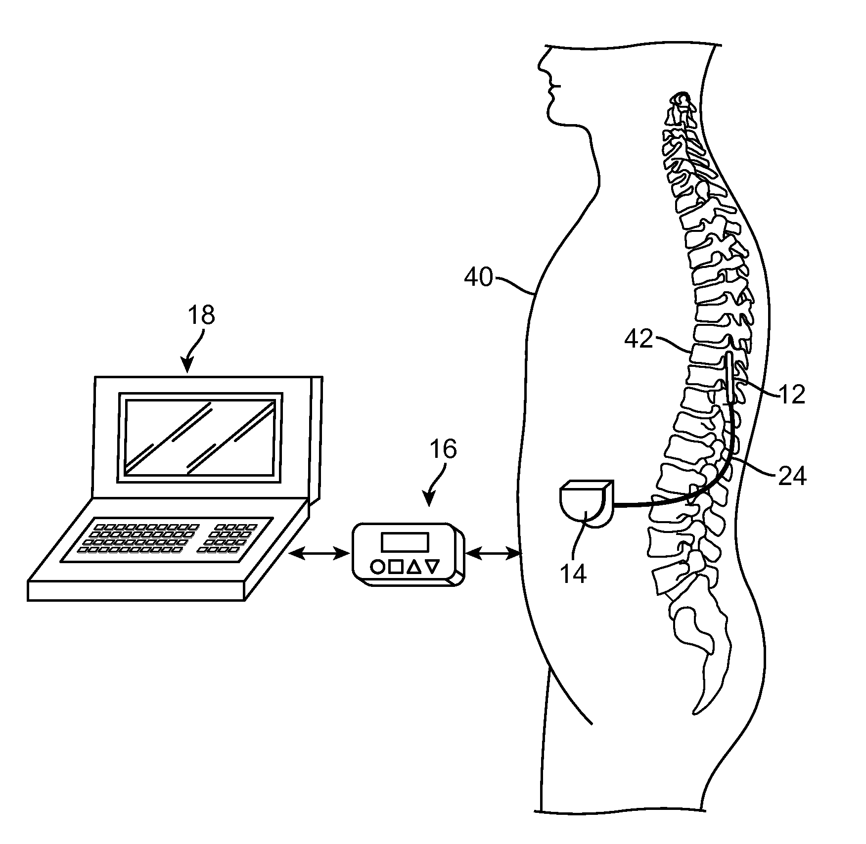
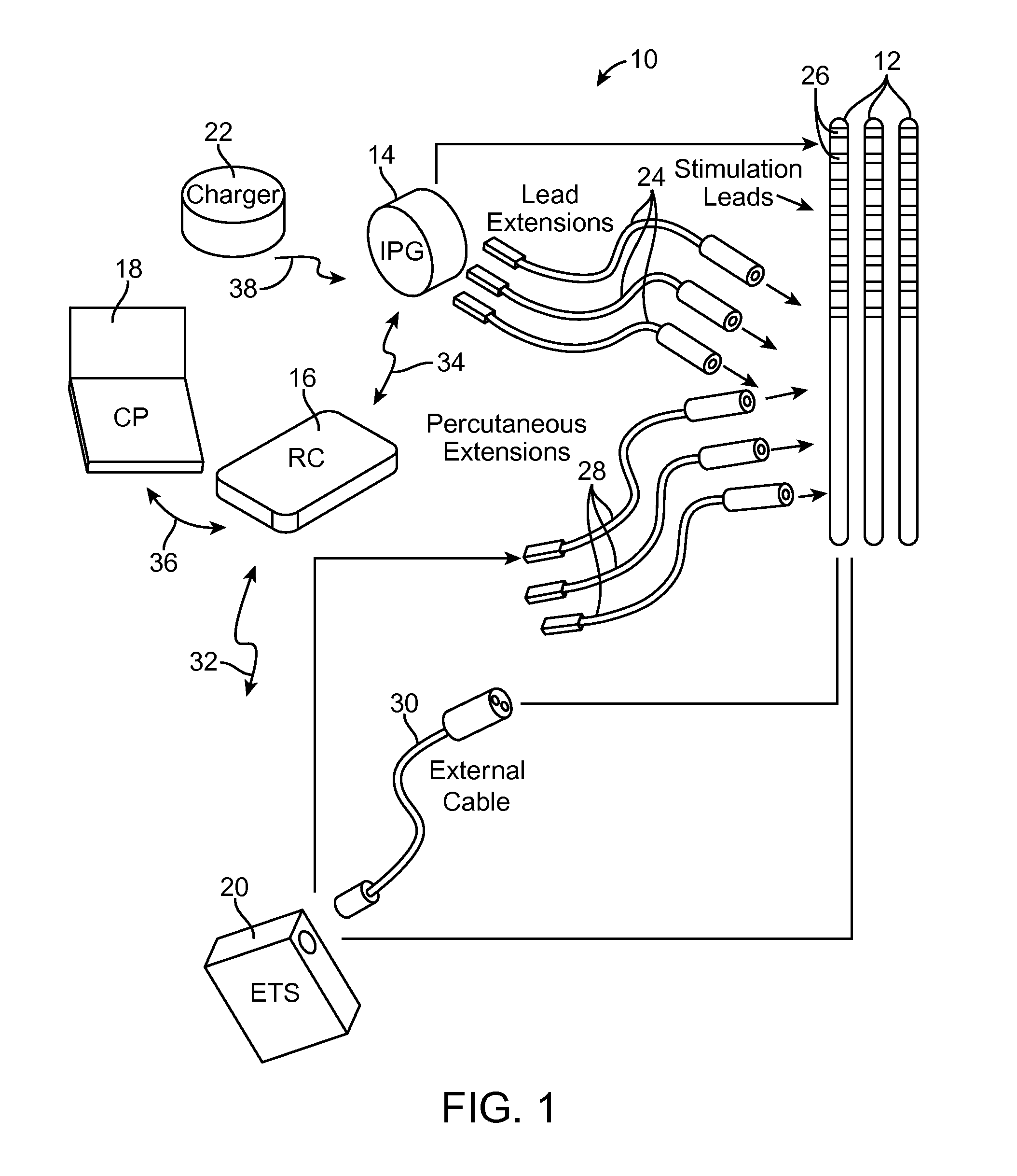
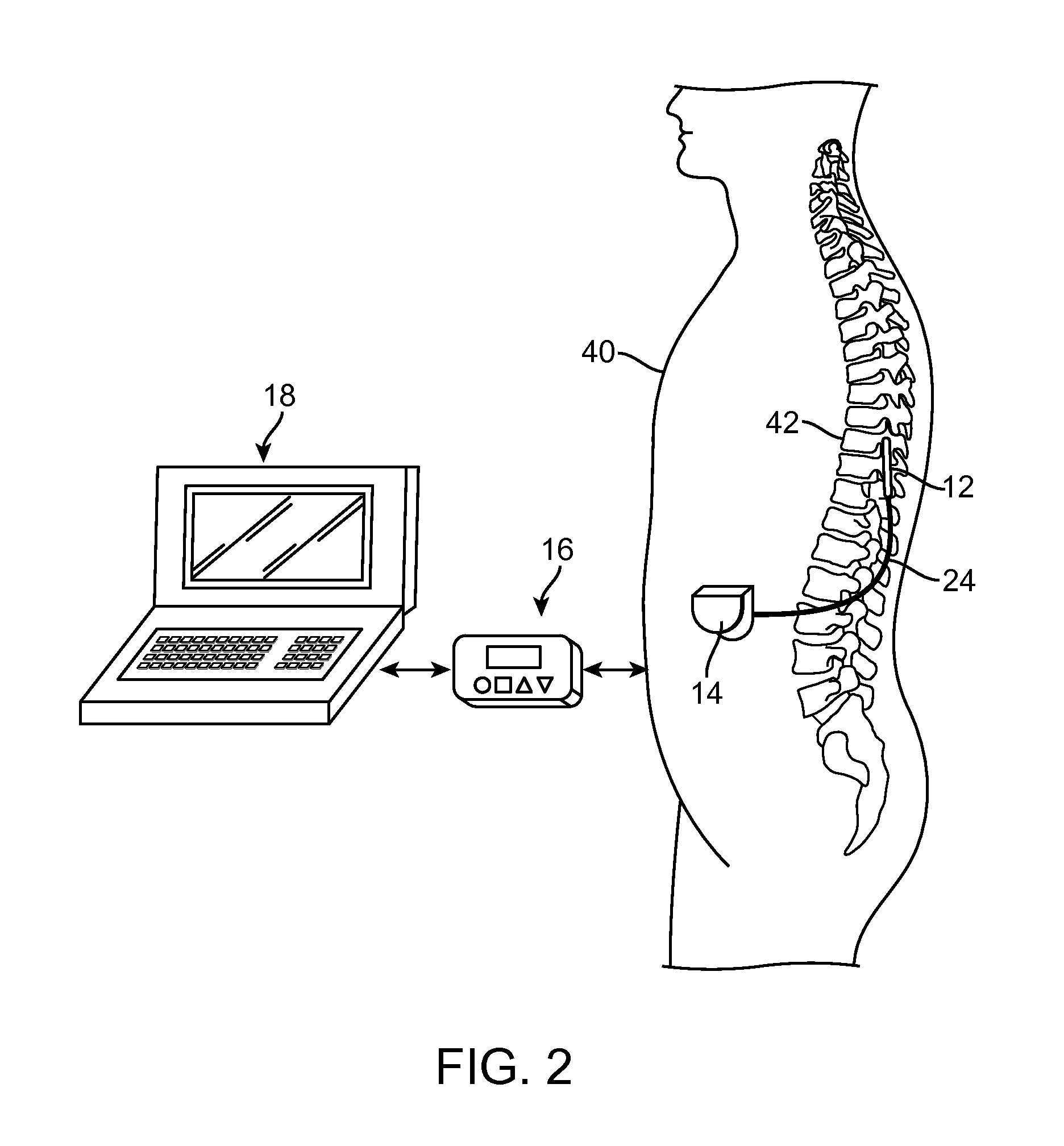
[0028]Turning first to FIG. 1, an exemplary spinal cord stimulation (SCS) system 10 generally includes one or more (in this case, three) implantable stimulation leads 12, a pulse generating device in the form of an implan...


PUM


Abstract

A neurostimulation comprises a plurality of electrical terminals configured for being respectively coupled to an array of electrodes, at least three configurable sources respectively coupled to at least three of the electrical terminals, and control circuitry configured for programming each of the at least three configurable sources to be either a current source or a voltage source. A method of providing neurostimulation therapy to a patient using an array of electrodes implanted adjacent neural tissue of the patient, comprises conveying electrical stimulation energy between a first one the electrodes and a second one of the electrodes, thereby creating an electrical field potential within the neural tissue, regulating a first current flowing through the first electrode, and regulating a first voltage at a third different one of the electrodes, thereby modifying a shape of the electrical field potential within the neural tissue.

Description

RELATED APPLICATION DATA[0001]The present application claims the benefit under 35 U.S.C. §119 to U.S. provisional patent application Ser. No. 61 / 611,951, filed Mar. 16, 2012. The foregoing application is hereby incorporated by reference into the present application in its entirety.FIELD OF THE INVENTION[0002]The present invention relates to tissue stimulation systems.BACKGROUND OF THE INVENTION[0003]Implantable neurostimulation systems have proven therapeutic in a wide variety of diseases and disorders. Pacemakers and Implantable Cardiac Defibrillators (ICDs) have proven highly effective in the treatment of a number of cardiac conditions (e.g., arrhythmias). Spinal Cord Stimulation (SCS) systems have long been accepted as a therapeutic modality for the treatment of chronic pain syndromes, and the application of tissue stimulation has begun to expand to additional applications such as angina pectoralis and incontinence. Deep Brain Stimulation (DBS) has also been applied therapeutical...

Claims


Application Information

Patent Timeline
IPC IPC(8): A61N1/36A61N1/05
CPCA61N1/36071A61N1/0551A61N1/36182A61N1/36125
Inventor PETERSON, DAVID K.L.
Owner BOSTON SCI NEUROMODULATION CORP
Learn More