Apparatus and methods for filtering emboli during precutaneous aortic valve replacement and repair procedures with filtration system coupled to distal end of sheath

a technology of emboli and filtration system, which is applied in the field of filtering emboli during interventional procedures, can solve the problems of embolic complication inherent risk of valve access, dilation, stroke or blindness, and does not disclose the removal method, so as to avoid traumatic sudden expansion and slow deliberate filter expansion

Inactive Publication Date: 2013-09-26
NEXEON MEDSYST
View PDF3 Cites 29 Cited by
  • Summary
  • Abstract
  • Description
  • Claims
  • Application Information

AI Technical Summary

Benefits of technology

[0013]In some embodiments, the filter has a compressed state and a deployed state. The apparatus may further include a guidewire and an introducer for use in percutaneously introducing the filter and the distal end of the sheath into the aortic arch. The introducer may include a tapered distal nose, a proximal end, a guidewire lumen configured to receive the guidewire, and a recess between the distal nose and the proximal end. The recess may be configured to receive the filter in the compressed state. The introducer may be configured for insertion within the lumen at the distal end of the sheath when the filter is expanded and coupled distally. The filter may be crimped into the recess during the manufacturing process and retained the compressed state within the recess. The introducer, the filter, and the distal end of the sheath may be percutaneously introducible into the aortic arch by pushing the introducer and sheath in their married position (or coupled together) over the guidewire. A control wire may be coupled to the introducer, and the control wire may be configured to advance the introducer while the sheath is maintained in position, allowing for slow deliberate expansion of the filter and avoiding traumatic sudden expansion and advancement out the end of the sheath. The introducer may be retrievable through the outlet of the filter and the lumen of the sheath after the filter expands to the deployed state by retracting the control wire. A portion of the sheath may be pre-curved to conform to the aortic arch, and the introducer may straighten the pre-curved portion of the sheath when inserted therein.
[0014]Under another aspect of the present invention, a method of filtering emboli during a percutaneous aortic valve replacement or repair procedure may include providing a sheath having proximal and distal ends and a lumen therebetween; and providing a filter coupled to the distal end of the sheath. The filter may have a compressed state and a deployed state, a frame, and an emboli-filtering mesh attached to the frame. The frame may have an inlet and an outlet, the inlet being configured to substantially span the aortic arch in a region between the aortic valve and the great arteries in the deployed state. The outlet of the filter is coupled to the distal end of the sheath within the aortic arch without leaving any gaps through which emboli could pass and without obstructing the lumen at the distal end of the sheath. The filter may be advanced through the previously positioned sheath via an introducer with a recess that will accommodate the filter and a control wire mechanism coupled to the introducer may be used to control expansion during deployment of the filter.

Problems solved by technology

One of the limitations for wide acceptance of this technology is the inherent risk of embolic complication during valve access, dilation and implantation.
The great vessels, which branch off the greater curve of the aortic arch, may transport such emboli to vulnerable locations like the eyes and brain causing stroke or blindness.
In addition embolic material can flow past the arch and occlude vessels to the spinal cord causing paralysis, to the bowel causing life threatening mesenteric ischemia / infarction, or to the renal vessels causing kidney failure, for example.
However, Shimon does not disclose how to remove the filter in such a manner as to prevent filtered emboli from re-entering the blood stream, nor so as to prevent additional emboli from being dislodged by the edges of the skeleton or the bows during removal.
Additionally, if additional devices are percutaneously introduced via the ascending aorta, such devices may scrape against the filter and thus potentially cause trauma to the aortic wall or dislodge emboli from the filter.
In any such device designed to deflect particles by resting on the greater curve of the arch there is also the issue of device interaction and entanglement since the typical valve is a high profile stiff catheter that will have significant outward bias along the greater curve during advancement across the arch.
This type of interaction could result in marriage of the devices together with catastrophic consequences as well as product incompetence if it folds up during catheter exchanges.
However, the square distal end of the delivery sheath may scrape the aortic arch as it is retrieved and thus potentially loosen additional occlusive material, such as emboli, from the aortic arch.
Additionally, because the sac spans the aorta when deployed, the sac may impede the physician's ability to percutaneously introduce other devices to the aorta because such devices may become trapped in the sac, or alternatively may create a gap between the edge of the sac and the aortic wall, thus providing an avenue for emboli or other occlusive material to bypass the sac.

Method used


Image

  • Apparatus and methods for filtering emboli during precutaneous aortic valve replacement and repair procedures with filtration system coupled to distal end of sheath
  • Apparatus and methods for filtering emboli during precutaneous aortic valve replacement and repair procedures with filtration system coupled to distal end of sheath
  • Apparatus and methods for filtering emboli during precutaneous aortic valve replacement and repair procedures with filtration system coupled to distal end of sheath

Examples


Embodiment Construction

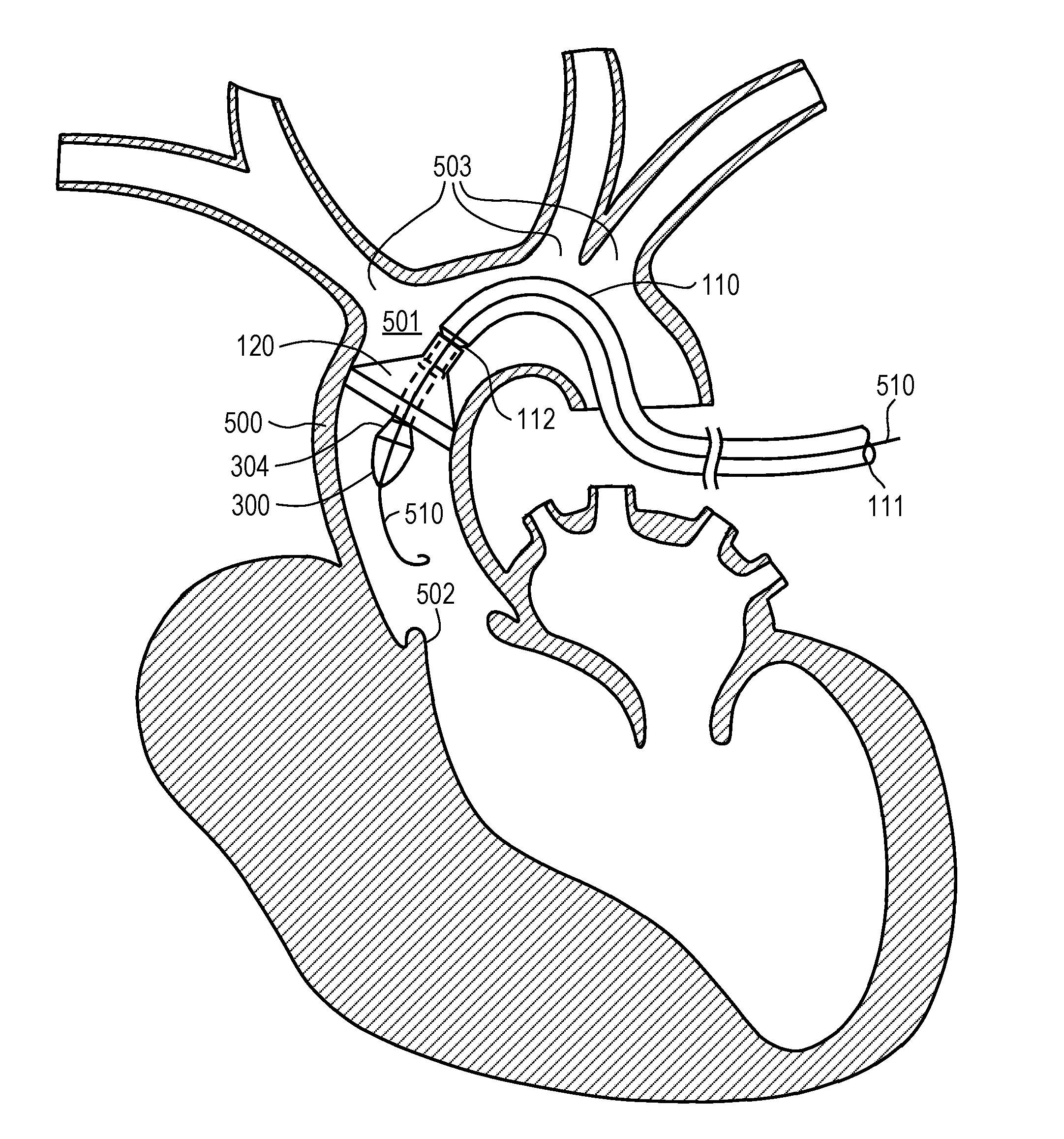
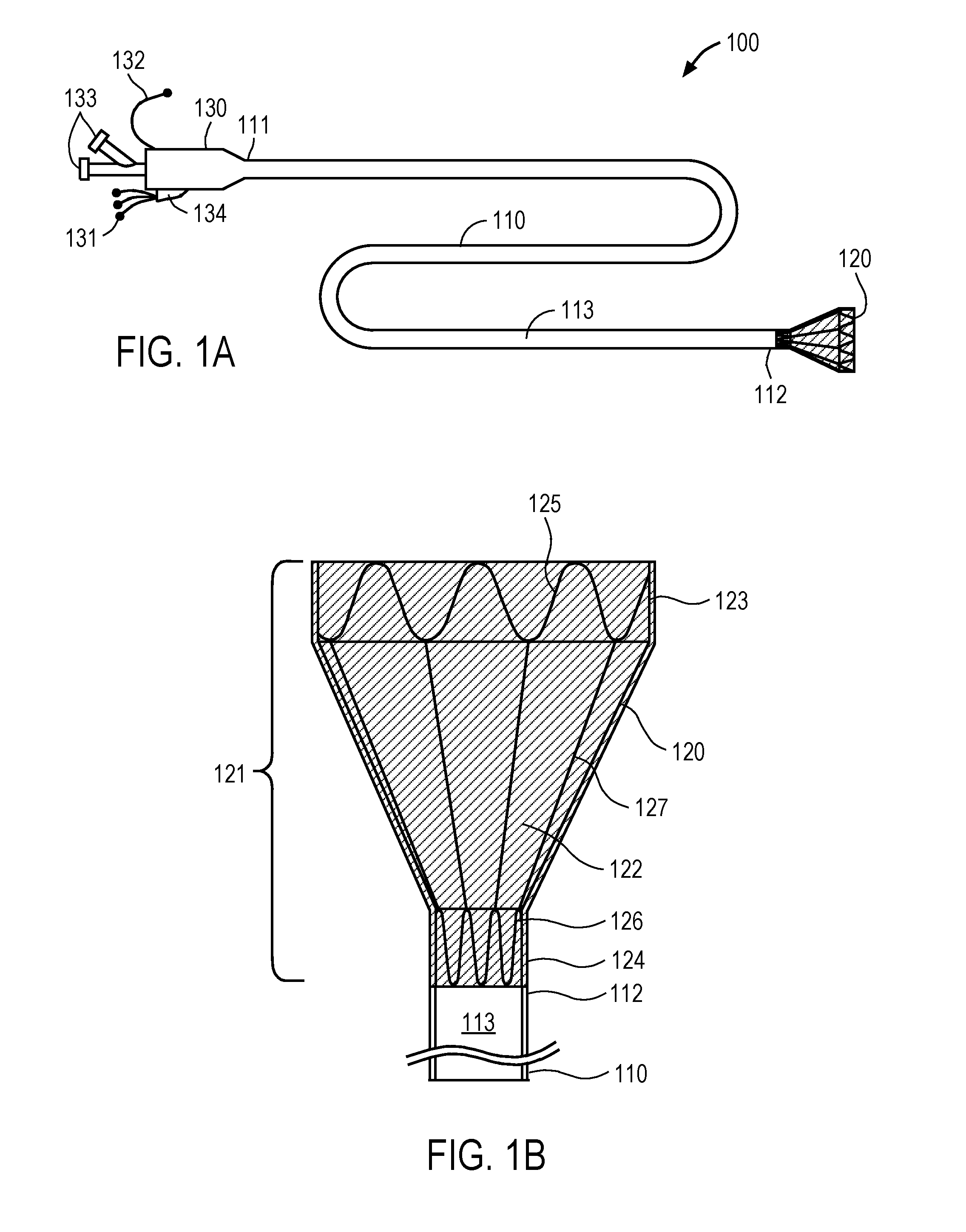
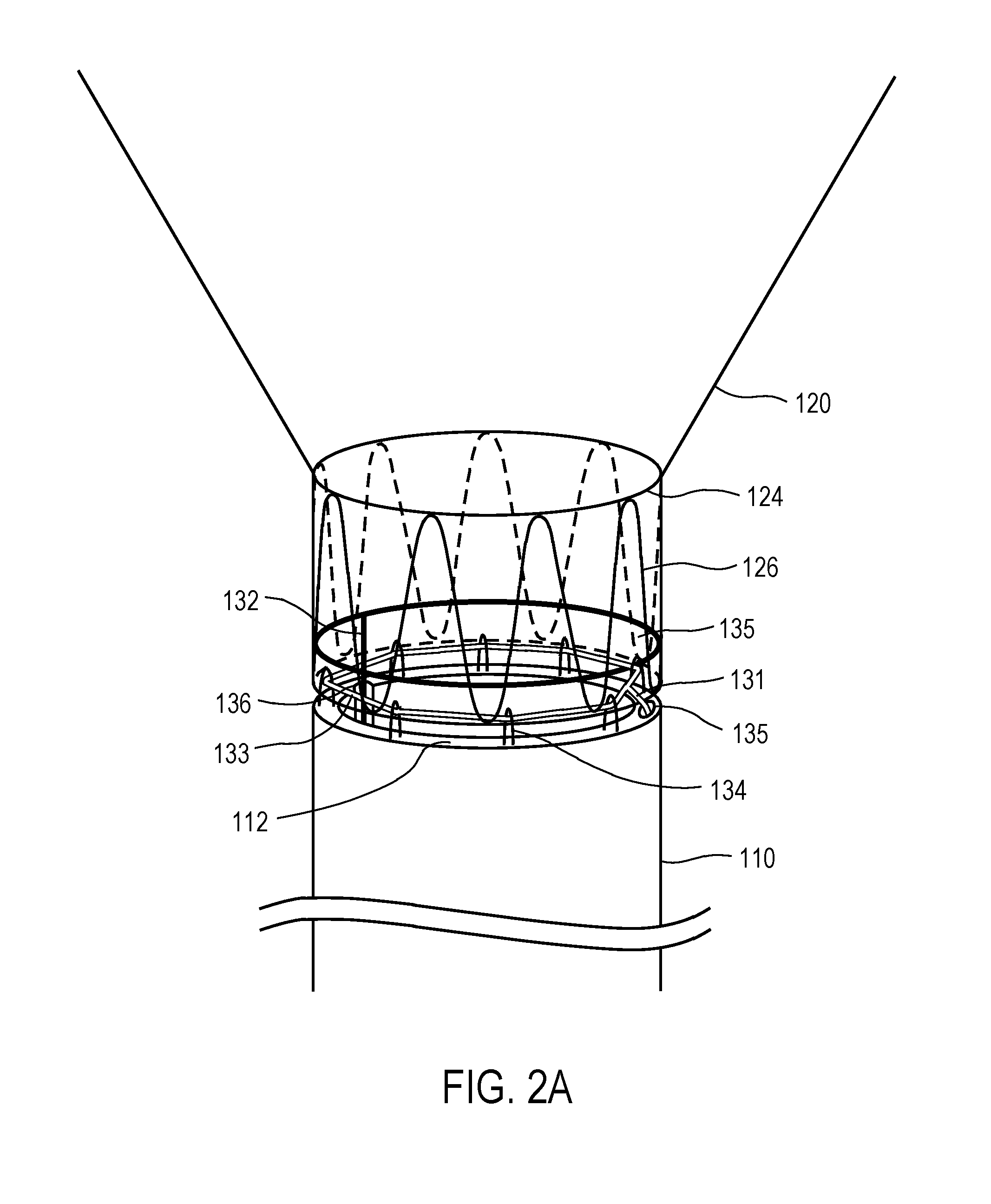
[0027]Embodiments of the invention provide embolic filters that readily may be used during percutaneous aortic valve replacement and repair procedures and that overcome the above-noted shortcomings of previously-known systems. The inventive filters may be coupled to the distal end of a sheath suitable for percutaneous delivery into the aorta, e.g., an 18 F sheath, and then compressed and mounted on an introducer that has a tapered nose and is disposed in the distal end of the sheath. The sheath, introducer, and compressed filter then are introduced to the aortic arch via the peripheral arterial system (e.g., femoral artery) and ascending aorta. The filter then is deployed from the distal end of the sheath by advancing the introducer relative to the sheath such that the filter expands to a deployed configuration at a location upstream of the great arteries, and the introducer then removed via the lumen of the sheath. The filter is securely coupled to the distal end of the sheath in s...


PUM


Abstract

Embodiments of the present invention provide apparatus and methods for embolic filtering during percutaneous valve replacement and repair procedures. Under one aspect, an apparatus comprises a sheath and a filter. The sheath has proximal and distal ends and a lumen therebetween. The distal end may be introduced into the aortic arch via the peripheral arteries and ascending aorta, while the proximal end may be disposed outside of the body. The lumen permits percutaneous aortic valve replacement or repair therethrough. The filter has a frame with an inlet and an outlet and an emboli-filtering mesh attached to the frame. The inlet is substantially spans the aortic arch in a region between the aortic valve and the great arteries. The outlet is coupled to the distal end of the sheath without leaving any gaps through which emboli could pass and without obstructing the lumen at the distal end of the sheath.

Description

CROSS-REFERENCE TO RELATED APPLICATIONS[0001]This application claims the benefit of priority of U.S. Provisional Application Ser. No. 61 / 613,896, filed Mar. 21, 2012.FIELD OF THE INVENTION[0002]This application generally relates to filtering emboli during interventional procedures, particularly percutaneous aortic valve replacement and repair procedures.BACKGROUND OF THE INVENTION[0003]The recent development of prosthetic valves that can be placed through a catheter into the heart without thoracotomy represents a significant advance in the field of cardiovascular medicine. Early results are very promising and overall reduction in mortality has been achieved with transcatheter aortic valve implantation (TAVI) in high surgical risk patients when compared to medical therapy. One of the limitations for wide acceptance of this technology is the inherent risk of embolic complication during valve access, dilation and implantation. For example, each guidewire, introducer, balloon, cutter, o...

Claims


Application Information

Patent Timeline
Patent Type & Authority Applications(United States)
IPC IPC(8): A61F2/01
CPCA61F2/013A61F2002/011A61F2/2427A61F2/011G10D3/01
Inventor BATES, MARK C.
Owner NEXEON MEDSYST
Why Eureka
Try Eureka