Catalyst deterioration diagnosis method, method for purification of exhaust gas using the diagnosis method, catalyst deterioration diagnosis apparatus, and apparatus for purification of exhaust gas using the diagnosis apparatus

Inactive Publication Date: 2013-10-03
TOYOTA CENT RES & DEV LAB INC
View PDF2 Cites 8 Cited by
  • Summary
  • Abstract
  • Description
  • Claims
  • Application Information

AI Technical Summary

Benefits of technology

[0039]The present invention makes it possible to diagnose deterioration of a catalyst based on information directly obtained from a test catalyst in a simple and accurate manner, a metho

Problems solved by technology

However, such a thermal history detection sensor detects only aggregation of the noble metal, and cannot detect lowering in the oxygen storage/release performance.
However, when such a Cmax method is carried out, it is necessary to dispose air-fuel ratio sensors both upstream and downstream of a flow path of the exhaust gas flowing to the cat

Method used


Image

  • Catalyst deterioration diagnosis method, method for purification of exhaust gas using the diagnosis method, catalyst deterioration diagnosis apparatus, and apparatus for purification of exhaust gas using the diagnosis apparatus
  • Catalyst deterioration diagnosis method, method for purification of exhaust gas using the diagnosis method, catalyst deterioration diagnosis apparatus, and apparatus for purification of exhaust gas using the diagnosis apparatus
  • Catalyst deterioration diagnosis method, method for purification of exhaust gas using the diagnosis method, catalyst deterioration diagnosis apparatus, and apparatus for purification of exhaust gas using the diagnosis apparatus

Examples


synthesis example 1

Catalyst Synthesis Example 1

[0128]In accordance with the method described in Japanese Unexamined Patent Application Publication No. 2009-84061, a catalyst was prepared as follows. Specifically, first, a mixture liquid was prepared by dissolving 49.1 g of an aqueous cerium nitrate solution with a concentration of 28% by mass in terms of CeO2, 54.7 g of an aqueous zirconium oxynitrate solution with a concentration of 18% by mass in terms of ZrO2, and 1.2 g of a nonionic surfactant (manufactured by Lion Corporation, trade name: LEOCON) in 90 cc of ion-exchanged water, and coprecipitation was performed by adding, to this mixture liquid, ammonia water containing NH3 at 25% by mass, so that the amount of NH3 was 1.2 equivalents to the anions in the mixture liquid. Subsequently, the obtained coprecipitates were filtered, washed, dried at 110° C. Then, the coprecipitates were placed in a furnace, and calcined in the air at 1000° C. for 5 hours. Thus, a ceria-zirconia solid solution was obta...

preparation example 1

Catalyst Preparation Example 1

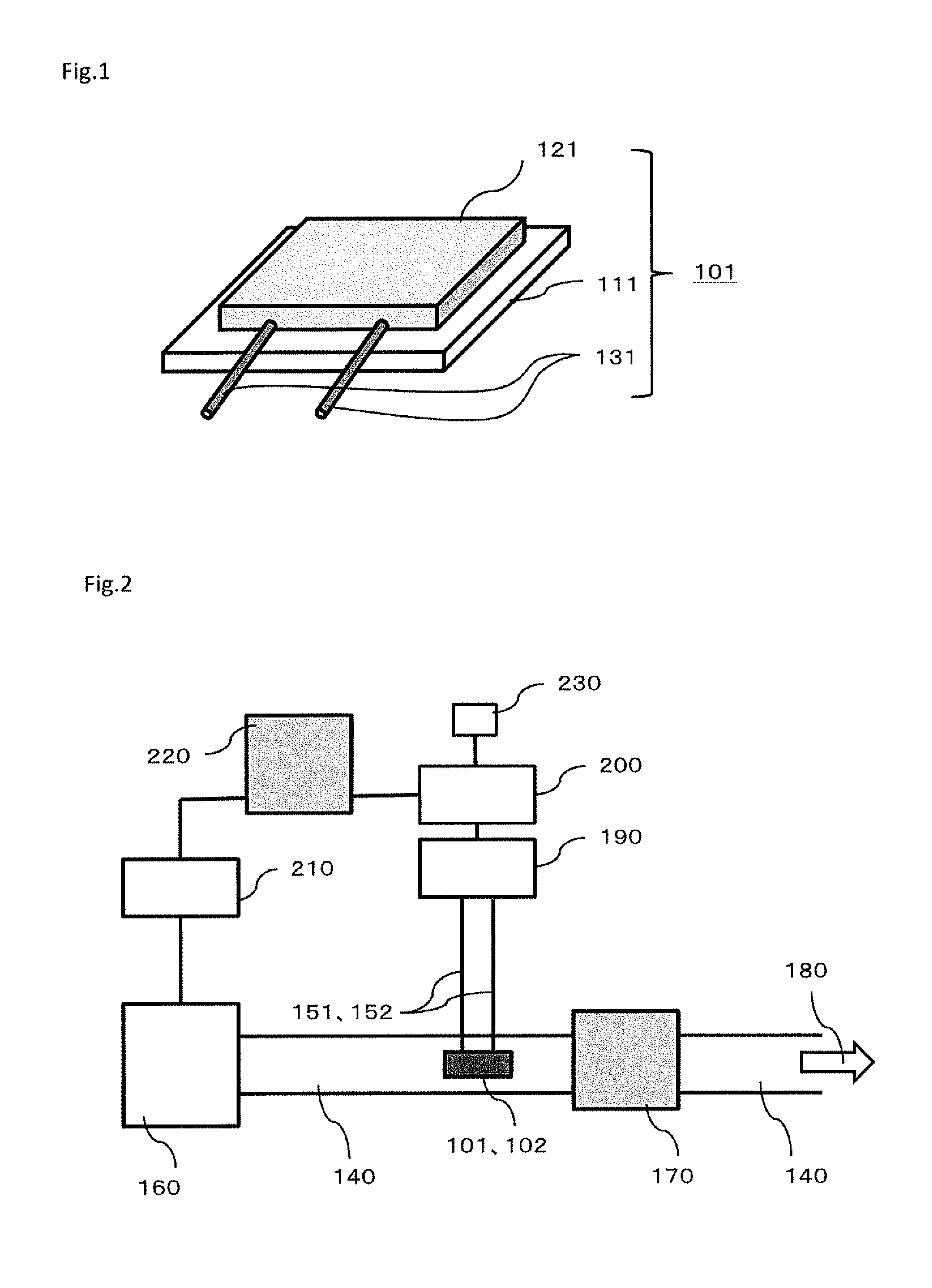
[0131]First, 2 parts by mass of the powder of the ceria-zirconia composite oxide obtained in Catalyst Synthesis Example 1 and 1 part by mass of ethylene glycol (manufactured by Tokyo Chemical Industry Co., Ltd., trade name: Polyethylene Glycol #300) were mixed with each other in a mortar to obtain a uniform paste. Subsequently, a substrate was fabricated by vapor-depositing two Pt wires having thicknesses of 2 mm on an alumina plate of 1 cm square, with the distance between the electrodes being 5.0 mm. The thickness of each of the Pt wires was approximately 200 nm. The paste was applied in a thickness of 0.1 mm onto the substrate, so that the Pt wires were covered with the paste. The paste was calcined in the air at 500° C. for 5 hours. Thus, a catalyst deterioration diagnosis element 1 was obtained. The oxygen storage / release amount of the catalyst (catalyst 1) in the catalyst deterioration diagnosis element 1 was 0.25 (mol-O2 / mol-Ce).

preparation example 2

Catalyst Preparation Example 2

[0132]A catalyst deterioration diagnosis element obtained in the same manner as in Catalyst Preparation Example 1 was subjected to a durability test of heating in the air under a temperature condition of 1100° C. for 5 hours. The catalyst deterioration diagnosis element after the durability test was termed as a catalyst deterioration diagnosis element 2. The oxygen storage / release amount of the catalyst (catalyst 2) in the catalyst deterioration diagnosis element 2 was 0.22 (mol-O2 / mol-Ce). (Catalyst Preparation Example 3)

[0133]A catalyst deterioration diagnosis element 3 was obtained in the same manner as in Catalyst Preparation Example 2, except that the temperature condition of the durability test was 1400° C. The oxygen storage / release amount of the catalyst (catalyst 3) in the catalyst deterioration diagnosis element 3 was 0.16 (mol-O2 / mol-Ce).


PUM


Abstract

A catalyst deterioration diagnosis method for diagnosing deterioration of a catalyst for purification of exhaust gas by using a test catalyst disposed in an exhaust gas flow path through which the exhaust gas flows, the method including an exhaust gas control step of inverting an air-fuel ratio of the exhaust gas in the flow path from a lean side to a rich side or from a rich side to a lean side; a measurement step of measuring a change over time in electrical resistance of the test catalyst at the inversion of the air-fuel ratio and finding a resistance change ratio of the test catalyst; and a determination step of determining catalytic deterioration of the test catalyst based on the resistance change ratio.

Description

CROSS-REFERENCE TO RELATED APPLICATIONS[0001]This application claims priority to Japanese Patent Application No. 2012-070749 filed on Mar. 27, 2012, the entire contents of which are incorporated by reference herein.BACKGROUND OF THE INVENTION[0002]1. Field of the Invention[0003]The present invention relates to a method for diagnosing deterioration of a catalyst used for purification of exhaust gas emitted from an internal combustion engine or for other purposes.[0004]2. Related Background Art[0005]Many catalysts for purification of exhaust gas have been developed so far for purification of harmful components emitted from internal combustion engines such as those of automobiles. For example, catalysts in which a noble metal such as platinum (Pt) and / or rhodium (Rh) is supported on a metal oxide support have been widely utilized as the catalysts for purification of exhaust gas. Moreover, catalysts have also been widely known in which a rare-earth metal oxide such as ceria or lanthana ...

Claims


Application Information

Patent Timeline
IPC IPC(8): F01N11/00
CPCF01N11/00F01N2550/02F01N2560/12F02D2200/0814Y02T10/47F02D41/1475F01N2900/1624Y02T10/40
Inventor SAKAMOTO, YOSHIYUKISUDA, AKIHIKOMORIKAWA, AKIRA
Owner TOYOTA CENT RES & DEV LAB INC
Why Eureka
Try Eureka