Variable valve actuator

Active Publication Date: 2013-10-03
NINGBO HOYEA MACHINERY MFG
View PDF2 Cites 2 Cited by
  • Summary
  • Abstract
  • Description
  • Claims
  • Application Information

AI Technical Summary

Benefits of technology

The present invention provides an actuator that can control the lift of an engine valve with greater accuracy, while using less energy and having a faster response time. The actuator also has reduced size and weight, making it easier to control and manage. Additionally, a new design is used for the valve release and snubbing, which improves the function and performance of the actuator. Overall, this invention offers improved performance and efficiency for engine valve control.

Problems solved by technology

Problems with an electromechanical camless system include difficulty associated with soft-landing, high electrical power demand, inability or difficulty to control lift, and limited ability to deal with high and / or varying cylinder air pressure.
An electrohydraulic camless system can generally overcome such problems, but it does have its own problems such as performance at high engine speeds and design or control complexity, resulting from the conflict between the response time and flow capability.
These requirements have stretched the limit of conventional electrohydraulic technologies.
As discussed above, there have been difficulties associated with electromechanical or electromagnetic latch-release devices.
The system just described has several potential problems.
The 2-way boost valve is driven by differential pressure inside the two cylinder chambers, or stroke spaces as the inventor refer as, and there is potentially too much time delay and hydraulic transient waves between the boost valve and cylinder chambers.
During a closing stroke, there is no effective means to add additional hydraulic energy until near the very end of the stroke, which may be a problem if there are too much frictional losses.
One drawback of the hydraulic spring is its rapid pressure drop once the engine valve movement starts.
Another common issue is the length of the actuator with the two compression springs separated by a hydraulic spring.
When the springs are aligned on the same axis, as disclosed in U.S. Pat. No. 5, 809,950, the total height may be excessive.
In the remaining patents of this family, the springs are not aligned on a straight axis, but are instead bent at the hydraulic spring, and the fluid inertia, frictional losses, and the transient hydraulic waves and delays may become serious problems.
Another common problem is that the closing stroke is driven by the spring pendulum energy only, and an existence of substantial frictional losses may pose a serious threat to the normal operation.
Much like the DaimlerChrysler disclosures, it has no effective means to add hydraulic energy at the beginning of a stroke to compensate for the engine cylinder air force and frictional losses.
It is not capable of adjusting valve lift either.

Method used


Image

  • Variable valve actuator
  • Variable valve actuator
  • Variable valve actuator

Examples


Embodiment Construction

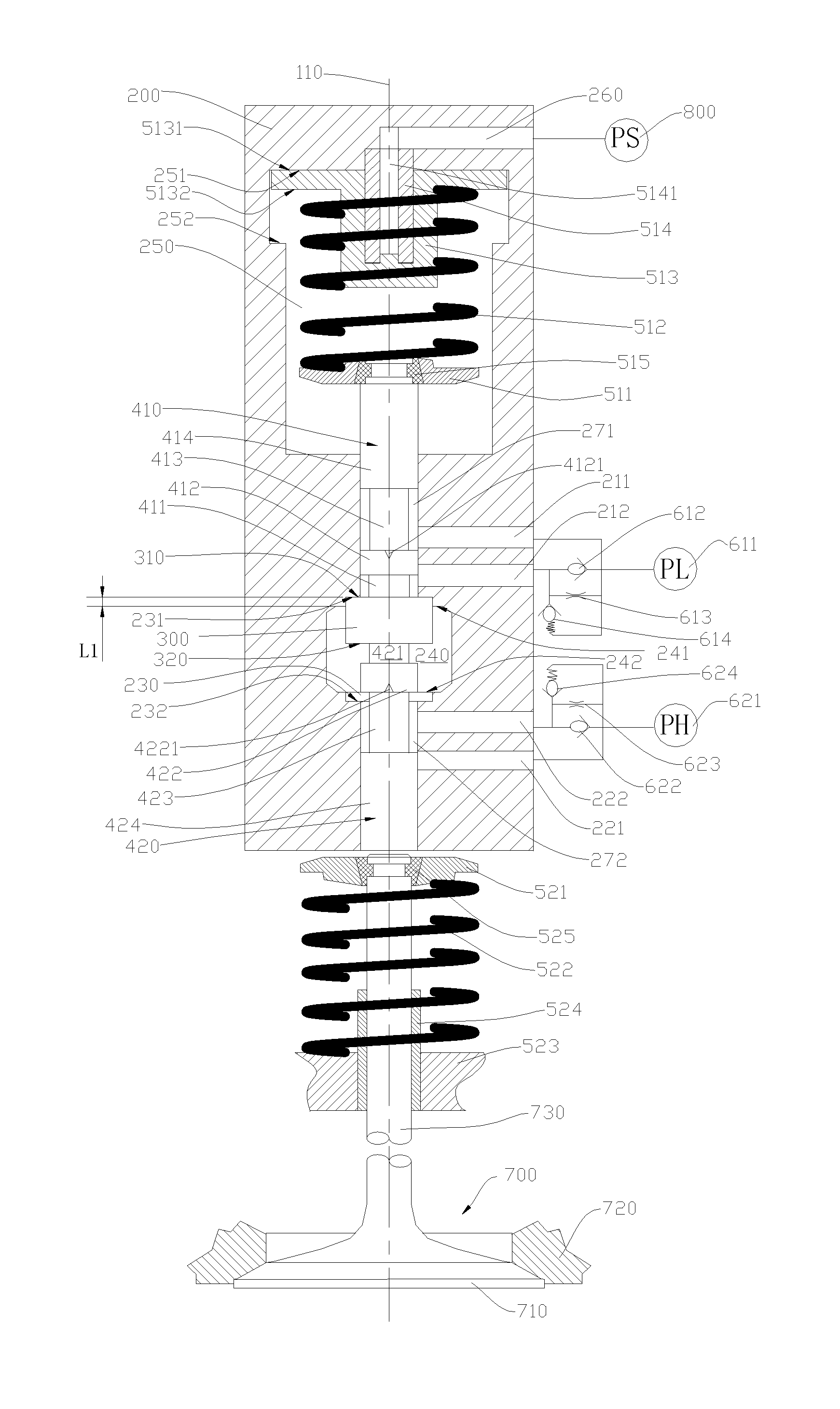
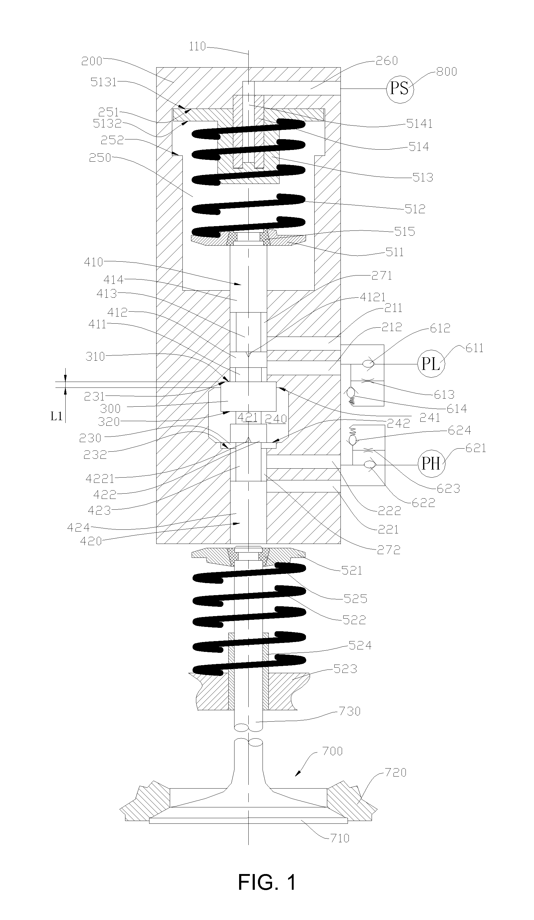
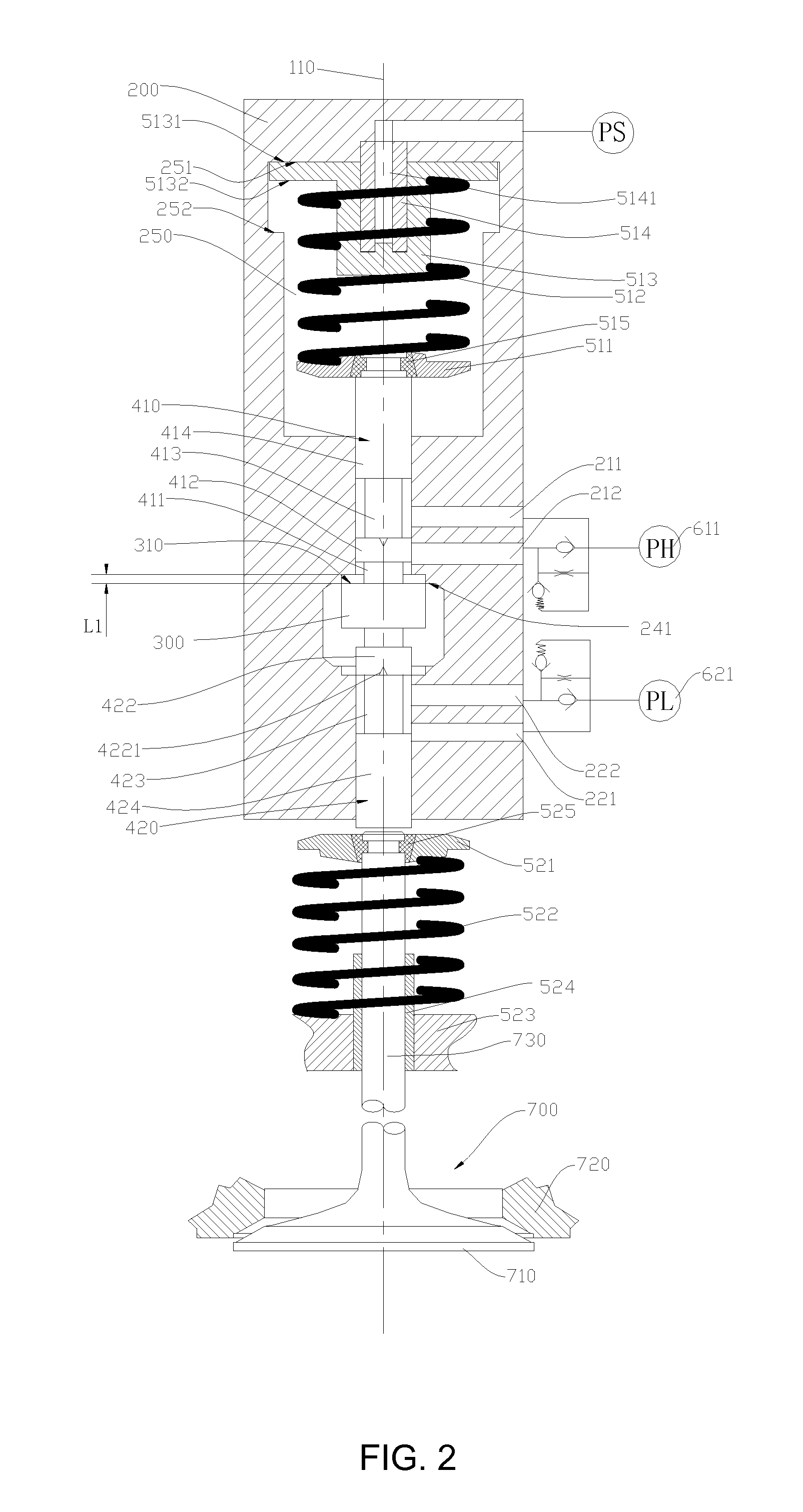
[0031]Please refer to FIG. 1 and FIG. 3, a preferred embodiment of the present invention, an actuator, comprises a housing 200; in the housing 200, in the second direction (from the top to bottom in the figures) along a longitudinal axis 110, a start port 260, a cavity 250, a first control passage 271, a first upper port 211, a second upper port 212, an actuation cylinder 230, a fluid bypass 240, a second lower port 222, a first lower port 221, and a second control passage 272; in the cavity 250, a first spring system (not labeled in FIGS. 1 and 3), a first piston rod 410 in the first control passage 271, an actuation piston 300 in the actuation cylinder 230 and the fluid bypass 240, a second piston rod 420 in the second control passage 272, and a second spring system (not labeled in FIGS. 1 and 3); an engine valve 700; a start hydraulic fluid source 800 connected to the start port 260, first hydraulic fluid source 611 connected to the upper port, and a second hydraulic fluid source...


PUM


Abstract

The present invention discloses an actuator, which is a combination of a hydraulic control unit and a spring-mass mechanical unit, comprising: a housing, with upper and lower ports; an actuation cylinder in the housing; an actuation piston in the actuation cylinder moveable along the longitudinal axis; a first fluid space; a second fluid space; a first piston rod connected to a first surface of the actuation piston; the second piston rod connected to a second surface of the actuation piston; a fluid bypass; a first spring system connected to the first piston rod, biasing the actuation piston in the second direction; a second spring system biasing the actuation piston in the first direction; a first flow mechanism; a second flow mechanism. The present invention also discloses two other preferred embodiments. The actuator features variable valve lift, low energy consumption, fast dynamic response, soft seating and easy controllability.

Description

REFERENCE TO RELATED APPLICATION[0001]This application claims the priority of the Chinese patent applications of serial no. 201210095184.5 and serial no. 201220136289.6, both of which were filed on Mar. 31, 2012, and the entire content of both of which are incorporated herein by reference.FIELD OF THE INVENTION[0002]This invention relates generally to actuators and corresponding methods and systems for controlling such actuators, and in particular, to actuators providing independent lift and timing control with minimum energy consumptionBACKGROUND OF THE INVENTION[0003]Various systems can be used to actively control the timing and lift of engine valves to achieve improvements in engine performance, fuel economy, emissions and other characteristics. Depending on the means of the control or the actuator, these systems can be classified as mechanical, electrohydraulic, and electromechanical (sometimes called electromagnetic). Depending on the extent of the control, they can be classifi...

Claims


Application Information

Patent Timeline
IPC IPC(8): F15B15/00F01L9/10
CPCF01L9/02F15B15/00F01L9/10
Inventor DENG, QIANGQUANLOU, ZHENGWEN, SHAO
Owner NINGBO HOYEA MACHINERY MFG
Why Eureka
Try Eureka