Method and apparatus for rapid adsorption-desorption co2 capture

a co2 and adsorption technology, applied in the direction of dispersed particle separation, membrane separation, separation processes, etc., can solve the problems of large equipment required for post-combustion configuration, difficult regeneration, and higher capital cos

Active Publication Date: 2013-10-03
ELECTRIC POWER RES INST INC
View PDF8 Cites 4 Cited by
  • Summary
  • Abstract
  • Description
  • Claims
  • Application Information

AI Technical Summary

Benefits of technology

[0014]According to another aspect of the invention, a method of capturing and sequestering a gas species from coal-fired power plant flue gas includes the steps of providing a polymer matrix embedded with a sorbent, placing the polymer matrix parallel to a flow of flue gas, and subjecting the flue gas to the polymer matrix to allow the sorbent to remove one or more gas species from the flue gas. The polymer matrix is adapted to be heated and cooled rapidly.

Problems solved by technology

Due to the low concentration of CO2 in the flue gas, low operating pressure, and large volume of flue gas to treat, the post-combustion configuration requires larger equipment and, hence, a higher capital cost.
However, current sorbent bed technologies require very large beds of granular sorbents, are difficult to regenerate, and require high energy consumption.
For TSA applications, CO2 is generally adsorbed at temperatures between 10° C. and 60° C. while regeneration is conducted at greater than 100° C. With large beds, it takes a long time to heat up (to regenerate, such as using steam) and cool down (for adsorption, such as using air) due to heat transfer limitations.
The steam used for heating also attacks some of the sorbents, especially if they condense and collect on the sorbent surface.
During the adsorption cycle, mass transfer and diffusion is a rate limiting step requiring very large beds to adsorb CO2 due to the large quantity of CO2 to be adsorbed and the large granules needed for the beds.
In addition, pressure drop across the beds is also a concern.
This results in a large amount of sorbent.

Method used


Image

  • Method and apparatus for rapid adsorption-desorption co2 capture
  • Method and apparatus for rapid adsorption-desorption co2 capture
  • Method and apparatus for rapid adsorption-desorption co2 capture

Examples


Embodiment Construction

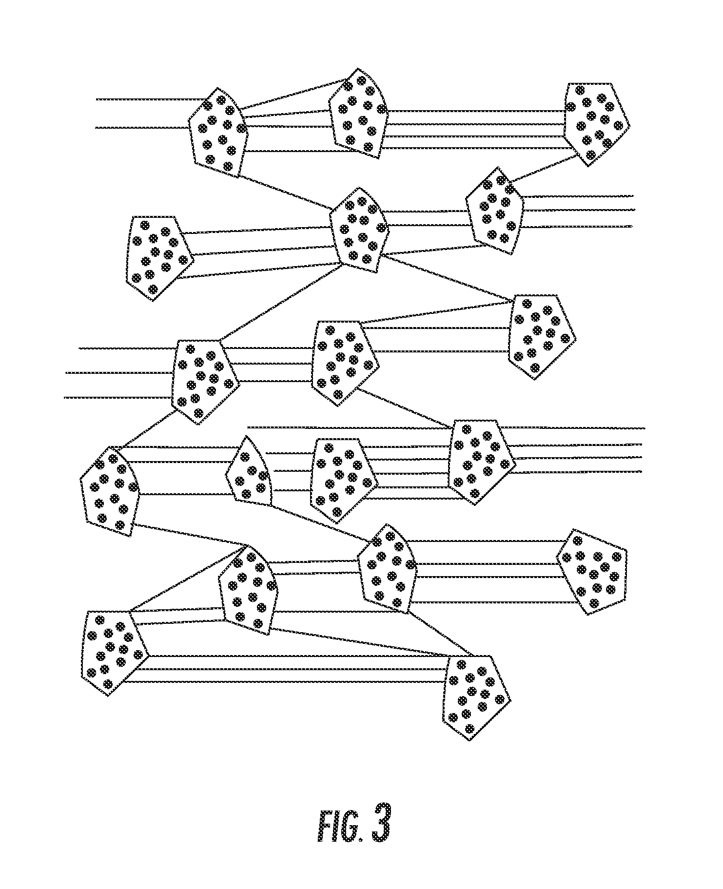
[0024]A prior art process for embedding small sorbent granules in a polytetrafluoroethylene (PTFE) polymer matrix was developed by Gore, FIG. 3. The PTFE matrix stabilizes the sorbent while allowing for ready access to the sorbent particles. The presence of the PTFE, a hydrophobic polymer, keeps water away from the sorbent surface. This helps to prevent any sorbent pore pluggage or chemical attack. Since sorbents can be readily embedded in relatively thin sheets of a PTFE tape, any gas phase components can easily access the sorbents with minimal mass transfer resistance.

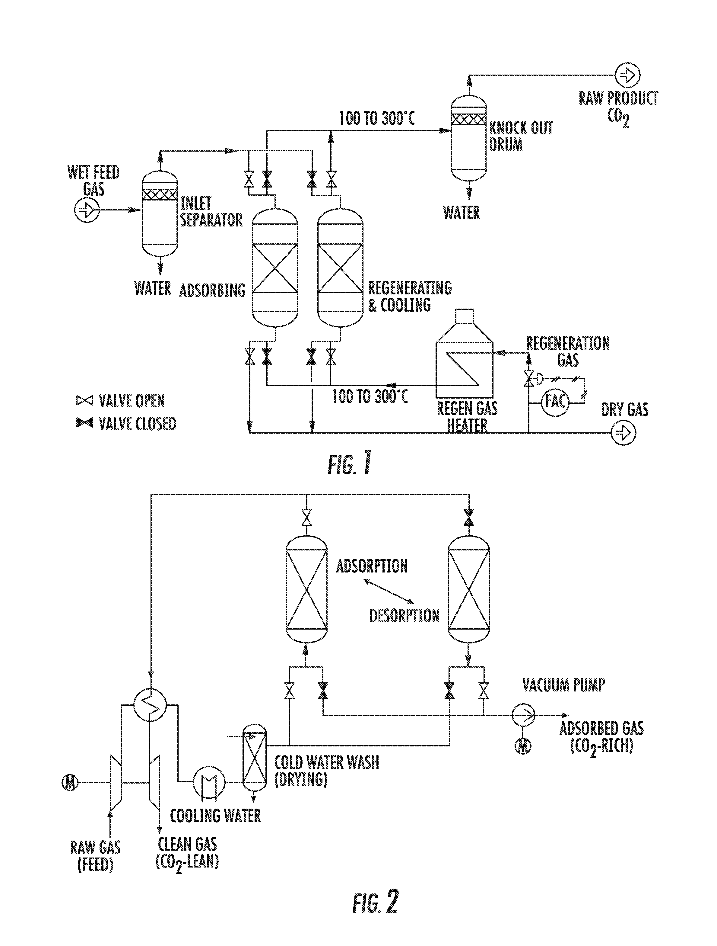
[0025]In adsorption-based separation processes, the two primary means to drive the separation are temperature and / or pressure. In the process, an adsorbent bed is subjected to changes in either or both of these to affect a separation of a mixture into its components.

[0026]In prior work, it has been shown that the key to minimizing the size of the adsorbent bed is to use devices that (1) setup flow channels that allow...


PUM

PropertyMeasurementUnit
temperaturesaaaaaaaaaa

Abstract

An apparatus for capture and sequestration of CO2 from fossil fuel-fired power plant flue gas includes a polymer matrix embedded with a sorbent suitable for removing CO2 from the flue gas and a spacer mated with the polymer matrix. The spacer is adapted to create channels between adjacent portions of the polymer matrix such that the flue gas flows through the channels and comes in contact with the sorbent. Further, an apparatus for the capture and sequestration of CO2 from fossil fuel-fired power plant flue gas includes a hollow fiber membrane embedded with an adsorbent or other suitable material for removing CO2 from the flue gas. The adsorbent particles may be embedded into a wall of the membrane.

Description

BACKGROUND OF THE INVENTION[0001]The present invention relates generally to a method and apparatus for rapid adsorption-desorption CO2 capture.[0002]The capture and sequestration of CO2 from fossil fuel-fired power plant flue gas is an important step in controlling global warming due to fossil plant energy production.[0003]CO2 separation and capture from flue gases of various stationary sources can be described by either post-combustion, pre-combustion, or oxy-combustion configurations. In the post-combustion configuration, CO2 is captured from the flue gas after the fuel is combusted. When air is used as an oxidant, the combustion flue gas is diluted with the nitrogen in the air; thus, the CO2 concentration in the post combustion flue gas is usually low and ranges from 10-15% by volume for a pulverized coal (PC) fired power plant. For each MW of electric generation capacity, a PC boiler produces a flue gas volume of about 3,500 acfm and emits roughly 1 ton of CO2 each hour. Due to ...

Claims


Application Information

Patent Timeline
Patent Type & Authority Applications(United States)
IPC IPC(8): B01D53/04
CPCB01D53/02B01D2259/45B01D53/229B01D53/62B01D2253/25B01D2253/342B01D2257/504B01D2258/0283B01D2259/4009B01D2259/402B01J20/261B01J20/28026B01J20/28033B01J20/3425Y02C10/04Y02C10/08Y02C10/10B01D53/0407B01D53/0462B01D53/047B01D2259/40028B01D53/228Y02A50/20Y02C20/40
Inventor CHANG, RAMSAYBERGER, ADAMBHOWN, ABHOYJIT
Owner ELECTRIC POWER RES INST INC
Why Eureka
Try Eureka