Fuel control method for hand-carried engine-driven working machine

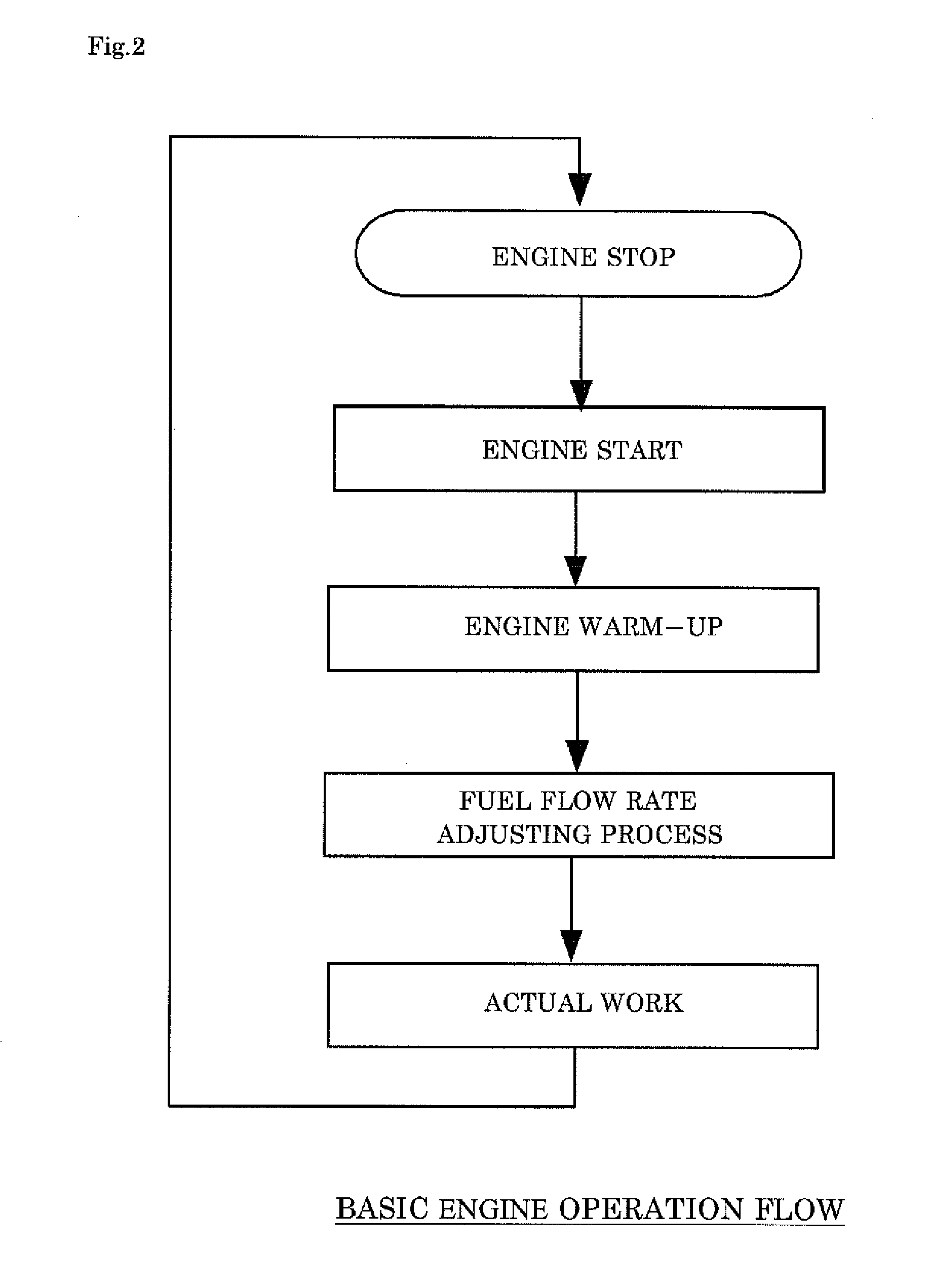
a technology of engine-driven working machine and operation control method, which is applied in the direction of electric control, speed sensing governor, machines/engines, etc., can solve the problems of deterioration of fuel economy, difficulty in preparing a precision engine speed measurement device at an outside working site, and reduction in engine output or exhaust emissions, so as to determine accurately the stable operating state of the engine and end the “fuel flow rate adjusting process”. , the effect of reliably and stably operation

Active Publication Date: 2013-10-03
IIDA ELECTRIC IND +1
View PDF0 Cites 19 Cited by
  • Summary
  • Abstract
  • Description
  • Claims
  • Application Information

AI Technical Summary

Benefits of technology

[0026]According to the configuration of the second aspect of the invention in which when the detected rotation speed deviates from the target rotation speed in the actual work, the opening of the solenoid valve is adjusted to the opening which results from adding to the “adjustment completion opening” (A.C.O.) which is obtained in the “fuel flow rate adjusting process” (F.F.R.A.P.) the “correction opening” (C.O.) which is determined from both of the “adjustment completion opening” (A.C.O.) and the detected rotation speed, the appropriate solenoid valve opening is set for each rotation speed within the working rotation speed range. This enables the engine to operate with the optimum air-fuel ratio over the whole of the working rotation speed range, and therefore, the engine is allowed to operate reliably and stably.
[0027]According to the configuration of the third aspect of the

Problems solved by technology

Regardless of the adjustment made by manufacturers, the optimum fuel combustion within an engine varies depending on various conditions such as the temperature and atmospheric pressure in an environment where a working machine is used, the kind of fuel used, the running-in condition of the engine, and the condition of an air cleaner (that is, whether or not it is clogged), and consequently the optimum driving

Method used


Image

  • Fuel control method for hand-carried engine-driven working machine
  • Fuel control method for hand-carried engine-driven working machine
  • Fuel control method for hand-carried engine-driven working machine

Examples


Embodiment Construction

[0035]Hereinafter, an embodiment of the invention will be described by reference to the drawings.

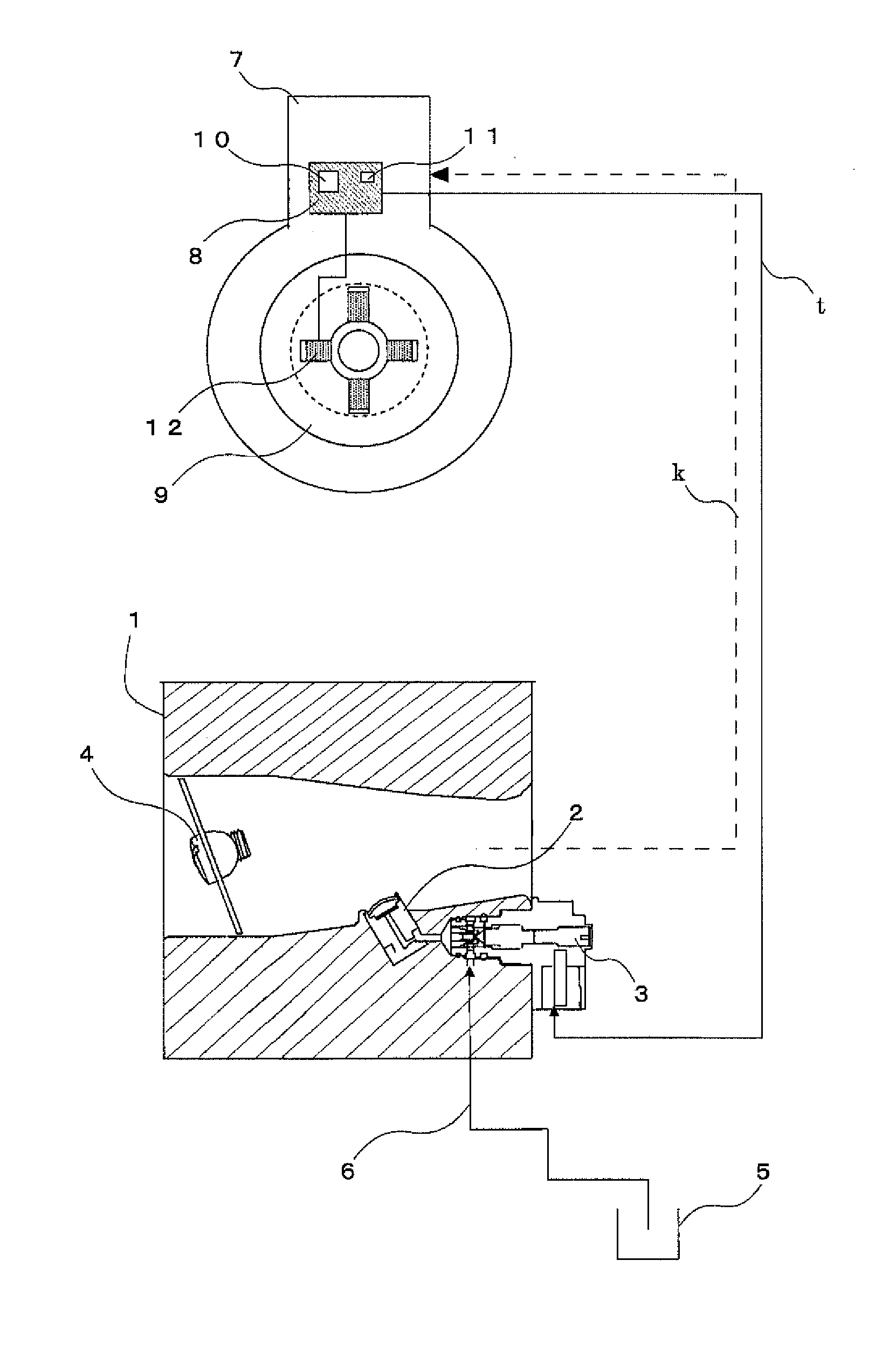
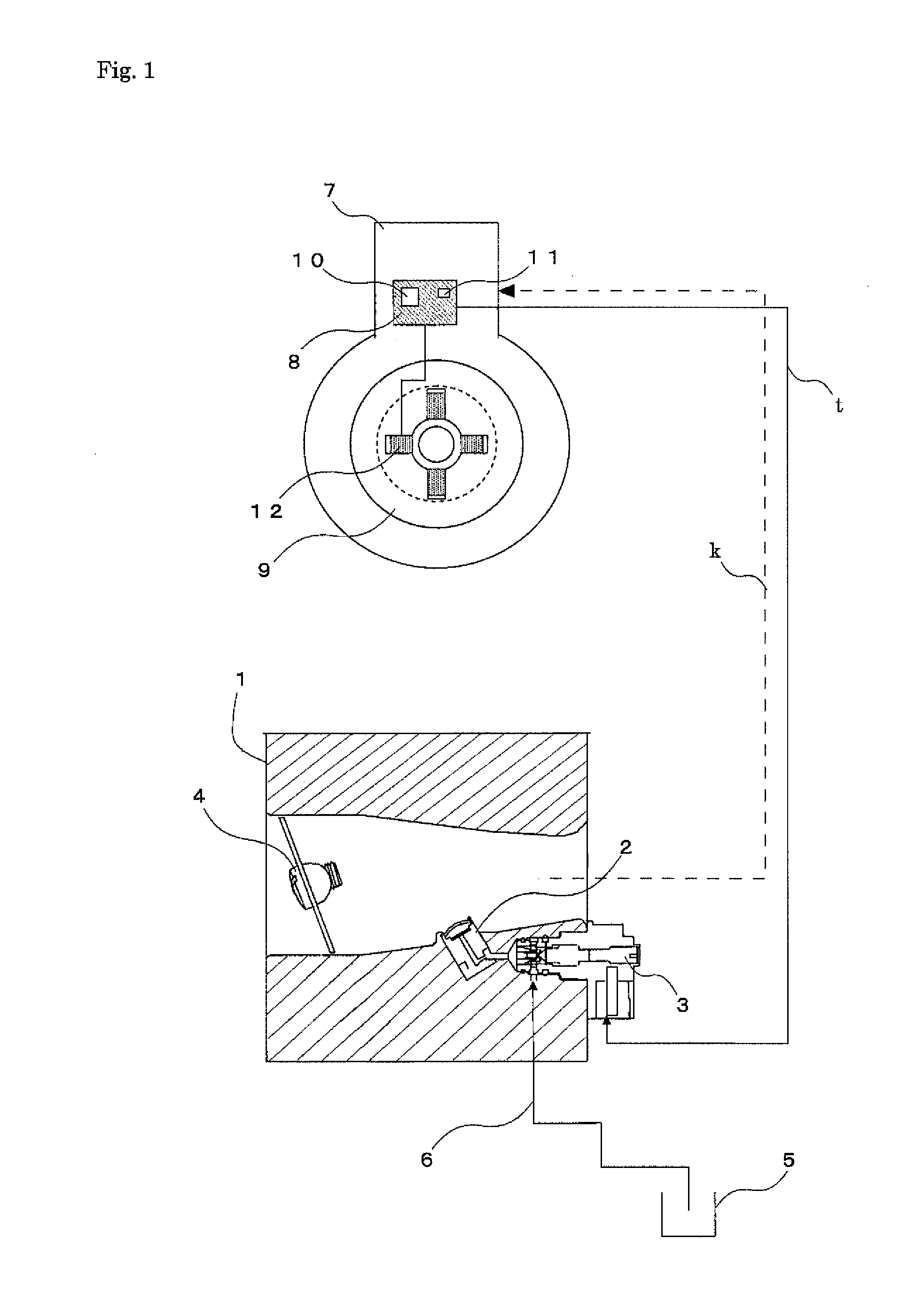
[0036]In FIG. 1, in an engine 7, by utilizing permanent magnets and charging coils 12 incorporated in a flywheel 9, an electric power is generated for inducing an electric spark in a spark plug and performing various controls in a microcomputer in a control unit 8. In addition, the electric power is also used for detecting a rotation speed of the engine 7 and driving a solenoid valve 3. The microcomputer in the control unit 8 detects a time per revolution and stores rotation speed data while the engine 7 is revolving.

[0037]In a carburetor 1, the solenoid valve 3 is connected between a measuring chamber and a main nozzle 2 and increases or decreases fuel to be supplied in response to a valve driving signal “t” from the control unit 8 to change the rotation speed of the engine 7. The solenoid valve 3 is connected to a fuel tank 5 via a fuel supply line 6. Reference numeral 4 denotes a thro...


PUM


Abstract

The opening of a solenoid valve is automatically adjusted after an engine is started and before actual work is performed for an appropriate air-fuel ratio, whereby it is possible to attain a good and stable driving of the engine without any delay even for an abrupt change in load.
After the engine is started, when a rotation speed enters a “fuel flow rate adjusting rotation speed range” in which a definite load is applied to the engine in a working rotation speed range of the engine in which a throttle valve is opened to a definite opening, a detected rotation speed is fed back to a target rotation speed, and the opening of the solenoid valve is controlled to adjust a fuel flow rate, so that the combustion state in the engine is optimized at the valve opening so determined.

Description

BACKGROUND OF THE INVENTION[0001]1. Field of the Invention[0002]The present invention relates to an operation control method for a hand-carried engine-driven working machine such as lawn mower or a chain saw.[0003]2. Description of the Related Art[0004]In hand-carried engine-driven working machines which are currently marketed, carburetors of engines are adjusted to correct a variation in performance for optimum engine driving before shipment from an engine assembly plant.[0005]Regardless of the adjustment made by manufacturers, the optimum fuel combustion within an engine varies depending on various conditions such as the temperature and atmospheric pressure in an environment where a working machine is used, the kind of fuel used, the running-in condition of the engine, and the condition of an air cleaner (that is, whether or not it is clogged), and consequently the optimum driving of the engine cannot be ensured any more, leading to a drawback of a deterioration of fuel economy, a...

Claims


Application Information

Patent Timeline
IPC IPC(8): F02M17/00
CPCF02M17/00F02M71/00F02P5/1455F02D41/08F02D2041/001F02D2200/0406F02M3/062F02D41/0002F02D31/007F02D31/009F02D2400/06F02M17/14
Inventor YAMASHITA, RYOUHEIYAMAZAKI, AKIRASAITOU, TAMOTSUWATANABE, HIDEKINONAKA, TAKUMI
Owner IIDA ELECTRIC IND
Why Eureka
Try Eureka