Vane segment and axial-flow fluid machine including the same

a technology of axial flow fluid and vane, which is applied in the direction of machines/engines, stators, liquid fuel engines, etc., can solve the problems of increasing the number of assembly steps of the vane segment. , to achieve the effect of reducing rattling, reducing the number of assembly steps, and reducing the deformation or cracking of the van

Active Publication Date: 2013-10-03
MITSUBISHI HEAVY IND LTD
View PDF6 Cites 11 Cited by
  • Summary
  • Abstract
  • Description
  • Claims
  • Application Information

AI Technical Summary

Benefits of technology

[0023]According to the present invention, it is possible to suppress deformation or cracking of the vane while reducing rattling between the plurality of vanes and reduce the number of assembly steps.

Problems solved by technology

However, since welding heat is applied to the vane, there is a problem in that deformation of the vane or cracking of a welded portion due to thermal stress may occur.
Further, in the vane segment described in Patent Document 1, since it is necessary to weld each of the plurality of vanes to the coupling member, there is also a problem in that the number of assembly steps of the vane segment increases.

Method used


Image

  • Vane segment and axial-flow fluid machine including the same
  • Vane segment and axial-flow fluid machine including the same
  • Vane segment and axial-flow fluid machine including the same

Examples


Embodiment Construction

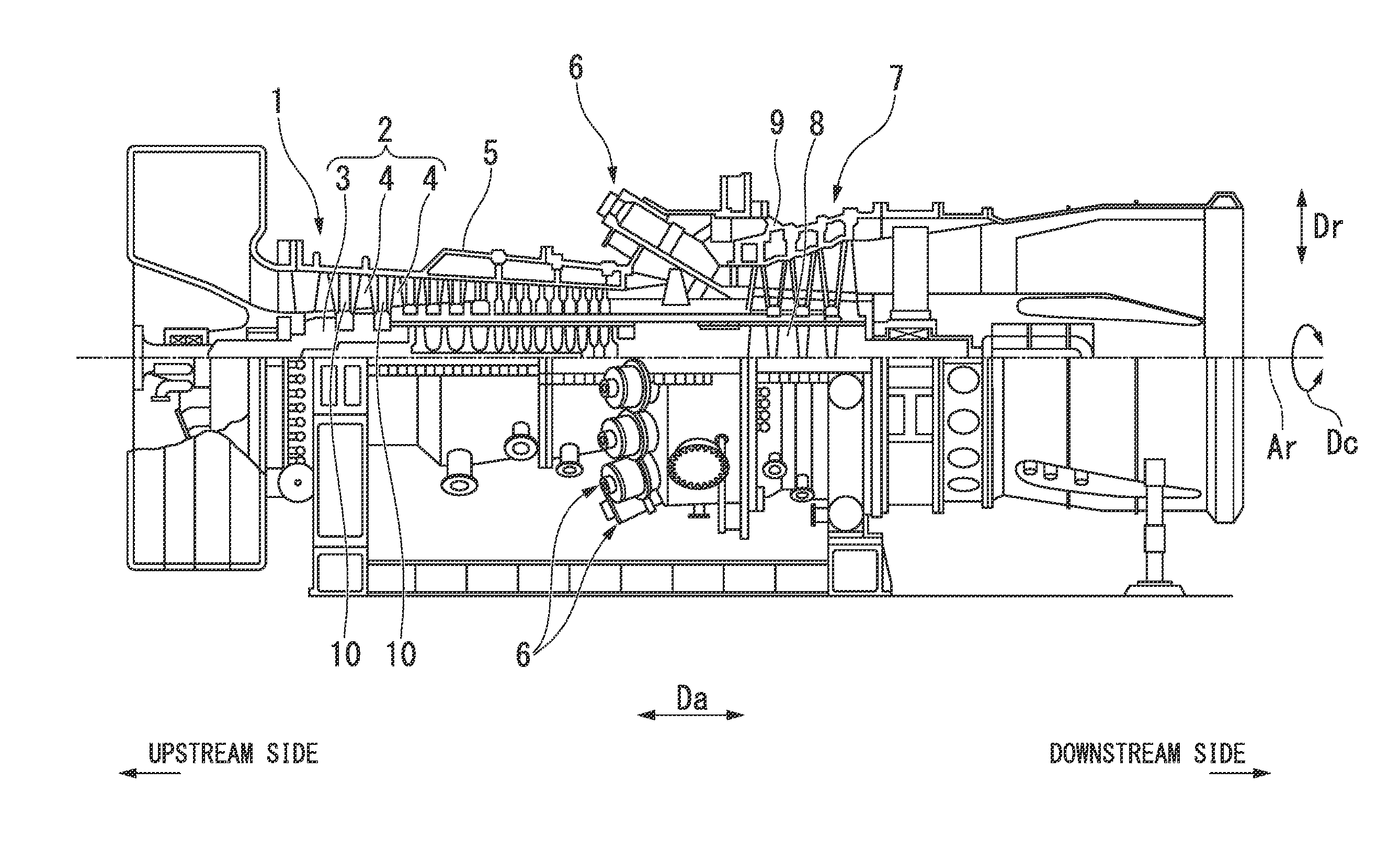
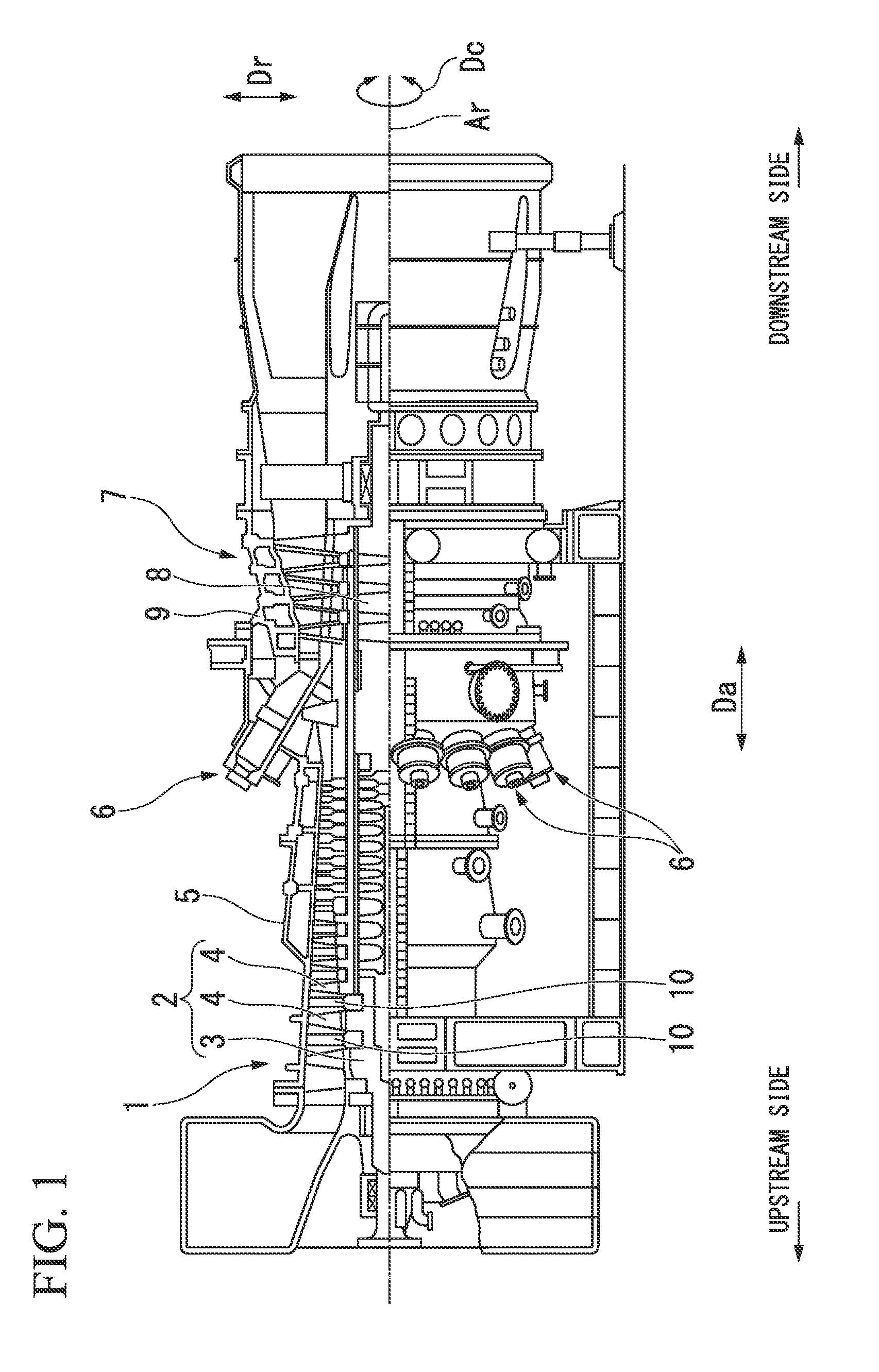
[0033]Hereinafter, an embodiment of an axial-flow fluid machine according to the present invention will be described in detail referring to FIGS. 1 to 8B.

[0034]A gas turbine includes a compressor 1 which compresses external air, thereby generating compressed air, a plurality of combustors 6 which mixes fuel from a fuel supply source with the compressed air and burns the mixture, thereby generating combustion gas, and a turbine 7 which is driven by the combustion gas, as shown in FIG. 1.

[0035]Both the compressor 1 and the turbine 7 are axial-flow fluid machines and include rotors 2 and 8 which rotate around an axis of rotation Ar, and casings 5 and 9 which cover the rotors 2 and 8. The compressor rotor 2 and the turbine rotor 8 rotate around the same axis of rotation Ar and are connected to each other. The plurality of combustors 6 are fixed to the turbine casing 9 at equal intervals in a circumferential direction Dc around the axis of rotation Ar.

[0036]In the following, a direction ...


PUM


Abstract

A vane segment according to the present invention includes: an outer connection member connecting a plurality of vanes; positioning jigs for positioning end vanes located at both ends, of the plurality of vanes; and radial restriction sections which restrict the outer connection member so as to be relatively immovable to an outer side in a radial direction of a vane ring, wherein: each of the plurality of vanes has a vane main body and an outer shroud; grooves are formed in the outer shrouds; openings into each of which the positioning jig is inserted are formed in portions of the outer connection member; holes into each of which the positioning jig inserted in the opening is inserted are formed in bottoms of the grooves of the two end vanes; and at least one of the positioning jigs is an eccentric positioning jig.

Description

BACKGROUND OF THE INVENTION[0001]1. Field of the Invention[0002]The present invention relates to a vane segment configuring a part of a vane ring, and an axial-flow fluid machine which includes the vane segment.[0003]Priority is claimed on Japanese Patent Application No. 2012-079253, filed on Mar. 30, 2012, the contents of which are incorporated herein by reference.[0004]2. Description of Related Art[0005]A gas turbine includes a compressor which compresses external air, thereby generating compressed air, a combustor which mixes fuel with the compressed air and burns the mixture, thereby generating combustion gas, and a turbine which is driven by the combustion gas.[0006]The compressor is an axial-flow fluid machine and includes a rotor which rotates around an axis of rotation, and a casing which covers the rotor. The rotor has a rotor main body which extends in an axial direction parallel to the axis of rotation, and a plurality of blade stages which are fixed to the outer peripher...

Claims


Application Information

Patent Timeline
Patent Type & Authority Applications(United States)
IPC IPC(8): F01D25/00
CPCF01D25/00F04D29/542F01D9/044F01D9/041F04D29/541F04D29/644
Inventor WAKI, KUNIHIKOARASE, KENICHI
Owner MITSUBISHI HEAVY IND LTD
Why Eureka
Try Eureka