Operation Support Apparatus, Electronic Device, Electronic Control Unit and Control System

a technology of operation support and electronic devices, which is applied in the direction of electrical control, data switching networks, instruments, etc., can solve the problems of increasing the manufacturing cost of electronic devices and a control system including electronic devices, complicated design of electronic devices, etc., and achieve the effect of suppressing the increase in manufacturing costs, and reducing the complexity of electronic devices

Inactive Publication Date: 2013-10-03
YAZAKI CORP
View PDF22 Cites 6 Cited by
  • Summary
  • Abstract
  • Description
  • Claims
  • Application Information

AI Technical Summary

Benefits of technology

[0020]According to the control system of the present invention, at least one of the electronic control units of the control system is configured as the electronic control unit of the present invention, and the electronic device is configured to transition to the pre-defined safe operation state upon reception of the predetermined operation state transition request control signal. That is, the operation support apparatus of at least one electronic control unit of the plurality of electronic control units provided to the control system transmits the operation state transition request control signal to the electronic device, which is controlled by the other electronic control unit having the failure, when the failure of the one or more other electronic control units is detected, and the electronic device shifts to the pre-defined safe operation state when the operation state transition request control signal is received. Therefore, it is possible to shift the electronic device to the safe operation state without mounting the function of detecting the failure of the electronic control unit controlling the electronic device and the like on the electronic device.
[0021]According to the operation support apparatus of the present invention, the operation support apparatus transmits the operation state transition request control signal to the electronic device, which is controlled by the electronic control unit, when the failure of the electronic control unit is detected, and the electronic device is configured to transition to the pre-defined safe operation state upon the reception of the operation state transition request control signal. Thereby, it is possible to shift the electronic device to the safe operation state without mounting the function of detecting the failure of the electronic control unit and the like on the electronic device. Hence, it is possible to configure the design of the electronic device and the hardware resources (memory, CPU) equivalently to those of the related art and to suppress the increase in the manufacturing costs of the electronic devices and the system including the same.
[0022]Also, according to the operation support apparatus of the present invention, since it is possible to rapidly notify the failure of the electronic control unit, it is possible to beforehand prevent a danger that may be caused due to the failure.
[0023]According to the electronic device of the present invention, the operation support apparatus of the electronic device transmits the operation state transition request control signal to the other electronic device, which is controlled by the electronic control unit, when the failure of the electronic control unit is detected, and the other electronic device is configured to transition to the pre-defined safe operation state upon the reception of the operation state transition request control signal. Thereby, it is possible to shift the electronic device to the safe operation state without mounting the function of detecting the failure of the electronic control unit and the like on the other electronic device. Hence, it is possible to configure the design of the other electronic device and the hard...

Problems solved by technology

Hence, a design of the electronic device becomes complicated and the throughput is increased to enhance hardware resources (such as ...

Method used


Image

  • Operation Support Apparatus, Electronic Device, Electronic Control Unit and Control System
  • Operation Support Apparatus, Electronic Device, Electronic Control Unit and Control System
  • Operation Support Apparatus, Electronic Device, Electronic Control Unit and Control System

Examples


first modified embodiment

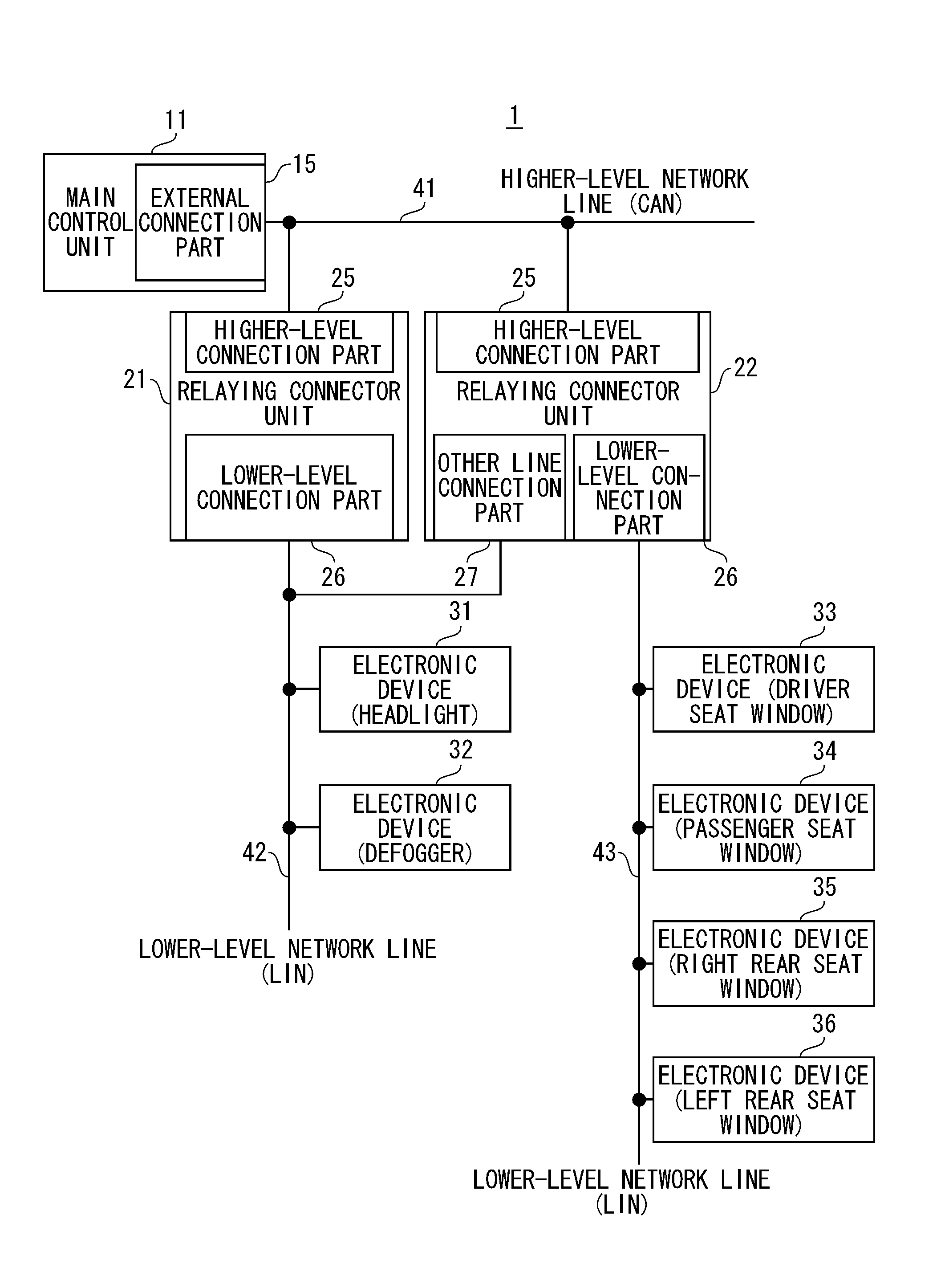
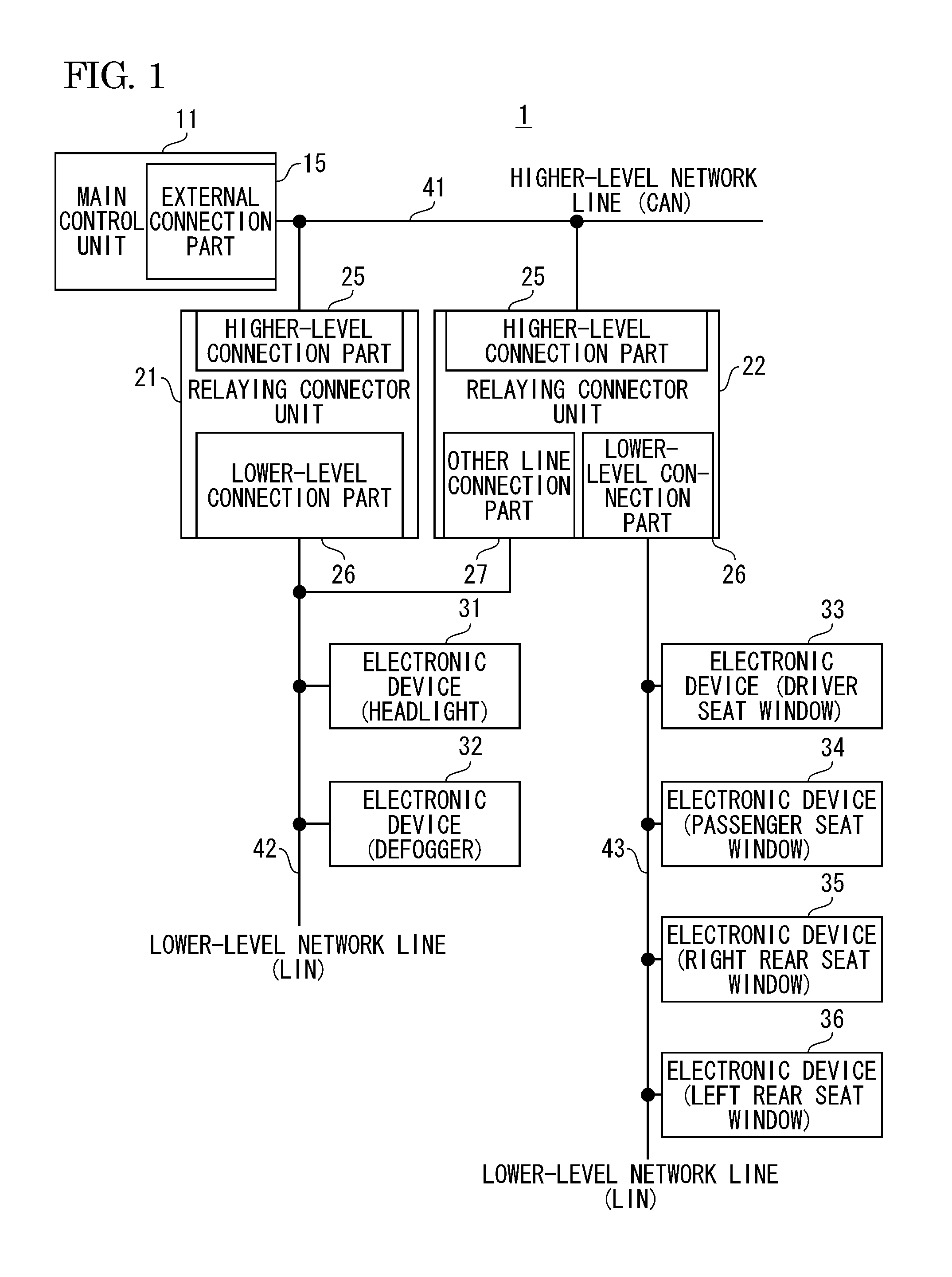
[0075]In the above illustrative embodiment, a vehicle control system 2 shown in FIG. 7 has a relaying connector unit 21′ having the same configuration as the relaying connector unit 21, instead of the relaying connector unit 22 of the vehicle control system 1, and an electronic device 31A that is configured to monitor the failure of the relaying connector unit 21 and upon detection of the failure, to transmit the operation state transition request control signal to the other electronic device 32, which is controlled by the relaying connector unit 21, instead of the electronic device 31.

[0076]That is, the vehicle control system 2 is configured to monitor the failure of the relaying connector unit 21 by the electronic device 31A and to support the operation of the other electronic device 32 that is controlled by the relaying connector unit 21 when detected the failure of the relaying connector unit 21.

[0077]Specifically, the electronic device 31A has the same configuration as the elec...

second modified embodiment

[0081]In the above illustrative embodiment, a vehicle control system 3 shown in FIG. 8 has a relaying connector unit 21′ having the same configuration as the relaying connector unit 21, instead of the relaying connector unit 22 of the vehicle control system 1, controls the electronic devices 33 to 36 connected to the lower-level network line 43 by the relaying connector unit 21′ and further has an operation support apparatus 51 connected to the lower-level network line 42.

[0082]The vehicle control system 3 is configured to monitor the failure of the relaying connector unit 21 and to support the operations of the electronic devices 31, 32, which are controlled by the relaying connector unit 21, upon the detection of the failure of the relaying connector unit 21, by the operation support apparatus 51.

[0083]The operation support apparatus 51 has a connector housing (not shown) and a microprocessor (MPU) 50 that is accommodated in the connector housing and operates in response to a pred...

third modified embodiment

[0090]In the above illustrative embodiment, a vehicle control system 4 shown in FIG. 10 has a new lower-level network that includes a relaying connector unit 23 having the same configuration as the relaying connector unit 21 of the vehicle control system 1, a plurality of electronic devices 37 to 39 and a lower-level network line 44 and performs the LIN communication. Also, the vehicle control system has a relaying connector unit 22A in which other line connection part 28 is newly added to the relaying connector unit 22, instead of the relaying connector unit 22. The new other line connection part 28 is connected to the lower-level network line 44.

[0091]The CPU 20a of the relaying connector unit 22A always receives the control signal, which flows through the lower-level network line 42 connected to the other relaying connector unit 21, to thus monitor whether the other relaying connector unit 21 is out of order, also always receives the control signal, which flows through the lower-...


PUM


Abstract

A vehicle control system has a main control apparatus, a plurality of relaying connector units, lower-level network lines provided in correspondence to the relaying connector units, and a plurality of electronic devices connected to the lower-level network lines. Moreover, the relaying connector unit monitors failure of the other relaying connector unit and upon detection of failure thereof, transmits an operation state transition request control signal, for transitioning the electronic apparatuses controlled by the other relaying connector unit to safe operation states which have been pre-defined for each of the electronic apparatuses, from an other line connection portion to the electronic apparatuses.

Description

CROSS REFERENCE TO RELATED APPLICATIONS[0001]This application is a continuation of PCT application No. PCT / JP2011 / 077180, which was filed on Nov. 25, 2011 based on Japanese Patent Application (No. 2010-264744) filed on Nov. 29, 2010, the contents of which are incorporated herein by reference.BACKGROUND OF THE INVENTION[0002]1. Field of the Invention[0003]The present invention relates to an operation support apparatus that supports an operation of an electronic device, which is controlled by a faulty electronic control unit, and relates to an electronic device, an electronic control unit and a control system having the operation support apparatus.[0004]2. Description of the Related Art[0005]A vehicle such as automobile and truck is mounted with a variety of electronic devices configuring a headlight, a defogger, an air conditioner, a power window and the like. The electronic devices are connected to an electronic control unit (ECU) consisting of a computer and the like through a wire...

Claims


Application Information

Patent Timeline
IPC IPC(8): F02D45/00
CPCF02D45/00B60H1/00978B60Q11/00F02D41/22H04L12/40006H04L12/4625H04L2012/40273F02D41/266F02D41/28G07C5/085
Inventor MAEJIMA, YOSHIMITSU
Owner YAZAKI CORP
Why Eureka
Try Eureka