
Immunity Against Temporary and Short Power Drops in Non-Volatile Memory: Pausing Techninques

a technology of non-volatile memory and immunity against temporary and short power drops, which is applied in the field of non-volatile semiconductor memory, can solve the problems of prone to mechanical failure, unsuitable mobile and handheld environment, and bulky disk drives

Active Publication Date: 2013-10-10
SANDISK TECH LLC
View PDF2 Cites 69 Cited by
  • Summary
  • Abstract
  • Description
  • Claims
  • Application Information

AI Technical Summary

Benefits of technology

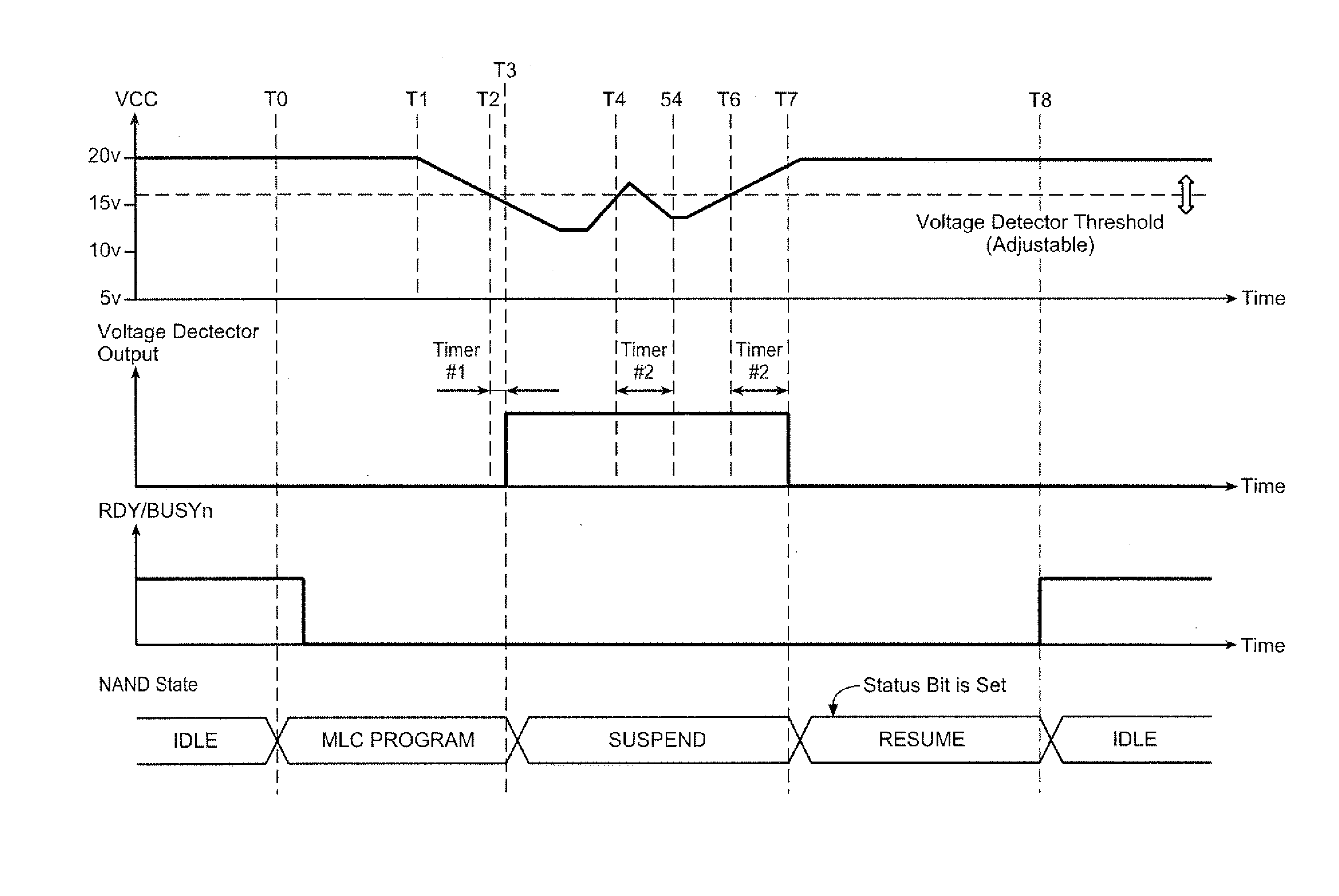
The present invention relates to a mechanism for protecting non-volatile memory circuits from temporary power drops. The mechanism includes a detection mechanism that monitors the voltage level of the power supply and suspends the operation of the memory circuit if the voltage level drops below a certain threshold for a set amount of time. This allows for self-protection during power drops that may occur due to hardware or software issues. The mechanism also allows for the memory circuit to resume its operation at a later time after the power supply has stabilized. Additionally, the invention includes a method for receiving a pause command and determining whether the operation being executed is pausable or not, and executing or delaying the pause command accordingly.

Problems solved by technology

Conventional mass storage, based on rotating magnetic medium such as hard drives and floppy disks, is unsuitable for the mobile and handheld environment.
This is because disk drives tend to be bulky, are prone to mechanical failure and have high latency and high power requirements.
These undesirable attributes make disk-based storage impractical in most mobile and portable applications.
This can result in loss of data and, in some cases, damage to the internal databases, possibly even leading to the failure of storage device initialization.

Method used


Image

  • Immunity Against Temporary and Short Power Drops in Non-Volatile Memory: Pausing Techninques
  • Immunity Against Temporary and Short Power Drops in Non-Volatile Memory: Pausing Techninques
  • Immunity Against Temporary and Short Power Drops in Non-Volatile Memory: Pausing Techninques

Examples


Embodiment Construction

Memory System

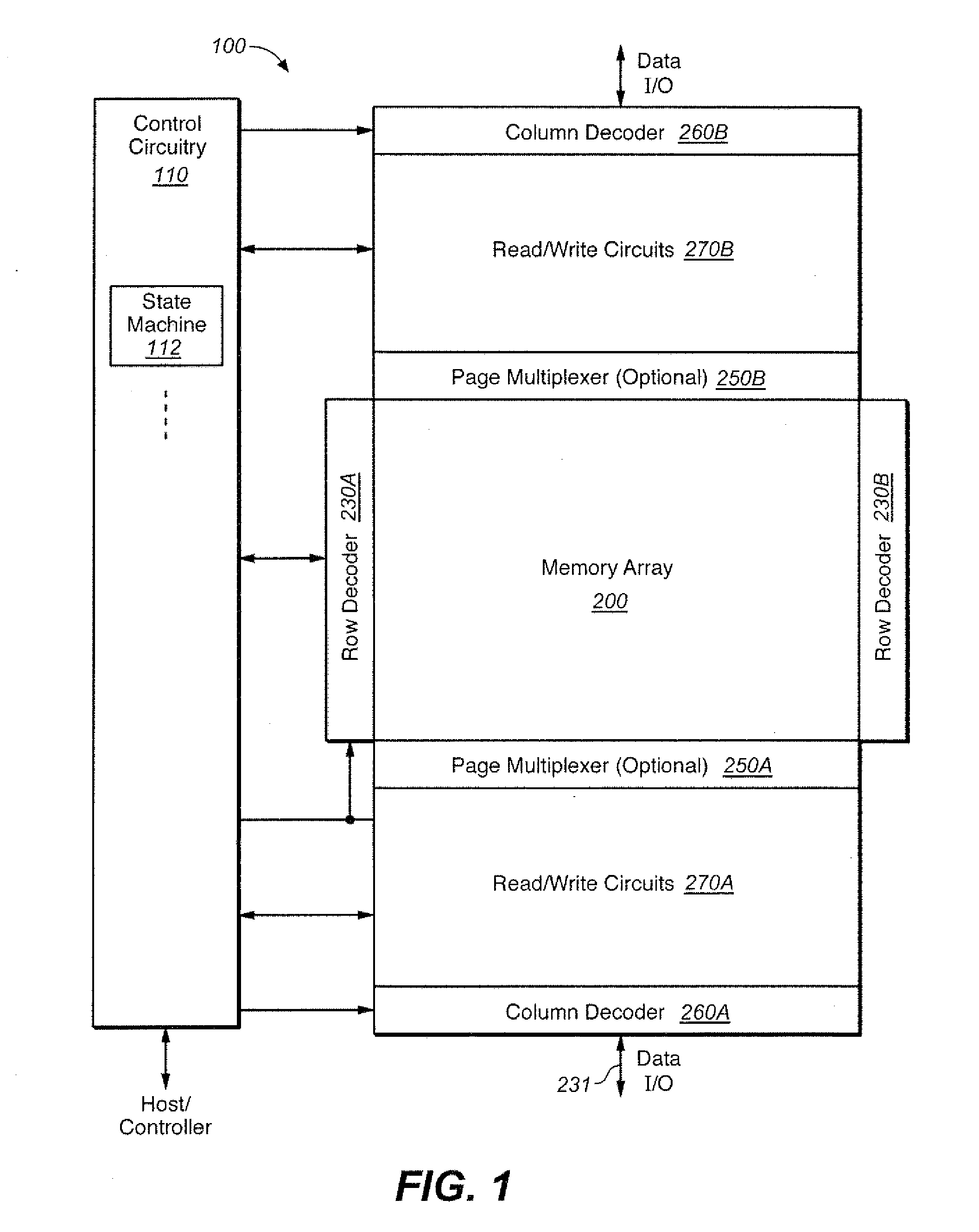
[0036]FIG. 1 to FIG. 11 illustrate example memory systems in which the various aspects of the present invention may be implemented.

[0037]FIG. 1 illustrates schematically the functional blocks of a non-volatile memory chip in which the present invention may be implemented. The memory chip 100 includes a two-dimensional array of memory cells 200, control circuitry 210, and peripheral circuits such as decoders, read / write circuits and multiplexers.

[0038]The memory array 200 is addressable by word lines via row decoders 230 (split into 230A, 230B) and by bit lines via column decoders 260 (split into 260A, 260B) (see also FIGS. 4 and 5.) The read / write circuits 270 (split into 270A, 270B) allow a page of memory cells to be read or programmed in parallel. A data I / O bus 231 is coupled to the read / write circuits 270.

[0039]In a preferred embodiment, a page is constituted from a contiguous row of memory cells sharing the same word line. In another embodiment, where a row of memo...


PUM


Abstract

A mechanism is presented memory circuits, such a NAND-type flash memories, to autonomously protect themselves from temporary and short power drops. A detection mechanism looks for the supply voltage to drop below a function voltage for a period of time. When such an event occurs, a suspend mechanism is activated, and after completing the last micro-operation (such as a program pulse) the memory freezes. When power is again stable at an operational level, the suspended operation is resumed. The memory controller can then be notified upon occurrence of such voltage drop by polling a special status bit. Examples of how the pausing can be implemented include altering of clock signals and suspending sub-phases of larger operations.

Description

CROSS-REFERENCE TO RELATED APPLICATION[0001]This application claims priority from U.S. Provisional Application No. 61 / 612,540, filed on Mar. 19, 2012, is related to a concurrently filed application [attorney docket number 008456-747US1] entitled “Immunity Against Temporary and Short Power Drops in Non-Volatile Memory” by Yacov Duzly, Alon Marcu, Farookh Moogat, Yan Li and Aaron Olbrich, which are hereby incorporated in its entirety by this reference.FIELD OF THE INVENTION[0002]This invention relates generally to non-volatile semiconductor memory such as electrically erasable programmable read-only memory (EEPROM) and flash EEPROM, and specifically to techniques of dealing with power level fluctuation.BACKGROUND OF THE INVENTION[0003]Solid-state memory capable of nonvolatile storage of charge, particularly in the form of EEPROM and flash EEPROM packaged as a small form factor card, has recently become the storage of choice in a variety of mobile and handheld devices, notably informat...

Claims


Application Information

Patent Timeline
IPC IPC(8): G11C7/22
CPCG11C16/0483G11C5/14G11C7/222G11C16/32G11C11/5628G11C11/5642G11C16/30G11C5/143
Inventor LI, YAN
Owner SANDISK TECH LLC
Learn More