Unit cell for flat-tubular solid oxide fuel cell or solid oxide electrolyzer, and flat-tubular solid oxide fuel cell and flat-tubular solid oxide electrolyzer using the same

Active Publication Date: 2013-10-10
KOREA INST OF ENERGY RES
View PDF2 Cites 4 Cited by
  • Summary
  • Abstract
  • Description
  • Claims
  • Application Information

AI Technical Summary

Benefits of technology

[0010]Therefore, an object of the present invention is to provide a unit cell for a flat-tubular solid oxide fuel cell or solid oxide electrolyzer including a plurality of unit

Problems solved by technology

Although the flat type exhibits high power density (power), a gas sealing area is large and thermal shock occurs due to a difference in the coefficient of thermal expansion between stacked materials, making it difficult to achieve a large-area device.
The cylindrical type is comparatively superior in terms of resistance to thermal stress and mechanical strength, and may achieve a large-area d

Method used


Image

  • Unit cell for flat-tubular solid oxide fuel cell or solid oxide electrolyzer, and flat-tubular solid oxide fuel cell and flat-tubular solid oxide electrolyzer using the same
  • Unit cell for flat-tubular solid oxide fuel cell or solid oxide electrolyzer, and flat-tubular solid oxide fuel cell and flat-tubular solid oxide electrolyzer using the same
  • Unit cell for flat-tubular solid oxide fuel cell or solid oxide electrolyzer, and flat-tubular solid oxide fuel cell and flat-tubular solid oxide electrolyzer using the same

Examples


Example

EXAMPLE 1

Unit Cell for Flat-Tubular Solid Oxide Fuel Cell or Solid Oxide Electrolyzer

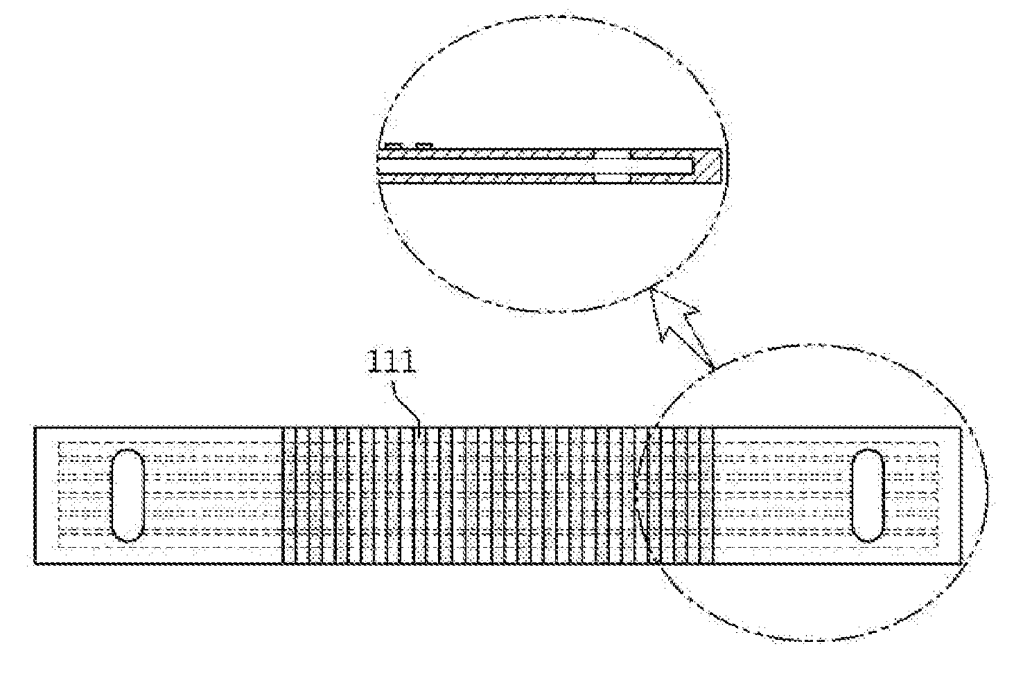
[0038]Using a ceramic extruder, an anode was formed so as to provide first gas passages therein, and both ends thereof were sealed. Subsequently, holes were formed in both ends of the dried body so that the first gas passages of unit cells were connected. As illustrated in FIG. 1, a connector 11 including a plurality of connection parts 111 spaced apart from each other and made of silicon carbide (SiC) was applied on the upper surface of the anode. As such, the connector may be manufactured using SiC bulk, SiC fiber composite, Crofer, Inconel, Ag, Au, Pt or perovskite ceramic (LSM, LSCF, etc.) tape, but the present invention is not limited thereto.

[0039]An electrolyte layer was applied on the surface of the anode not coated with the connector, after which heat treatment was performed at 1350˜1400° C. so that the connector and the electrolyte layer became dense. Subsequently, a cathode was applied ...

Example

EXAMPLE 2

Unit Cell for Flat-Tubular Solid Oxide Fuel Cell or Solid Oxide Electrolyzer

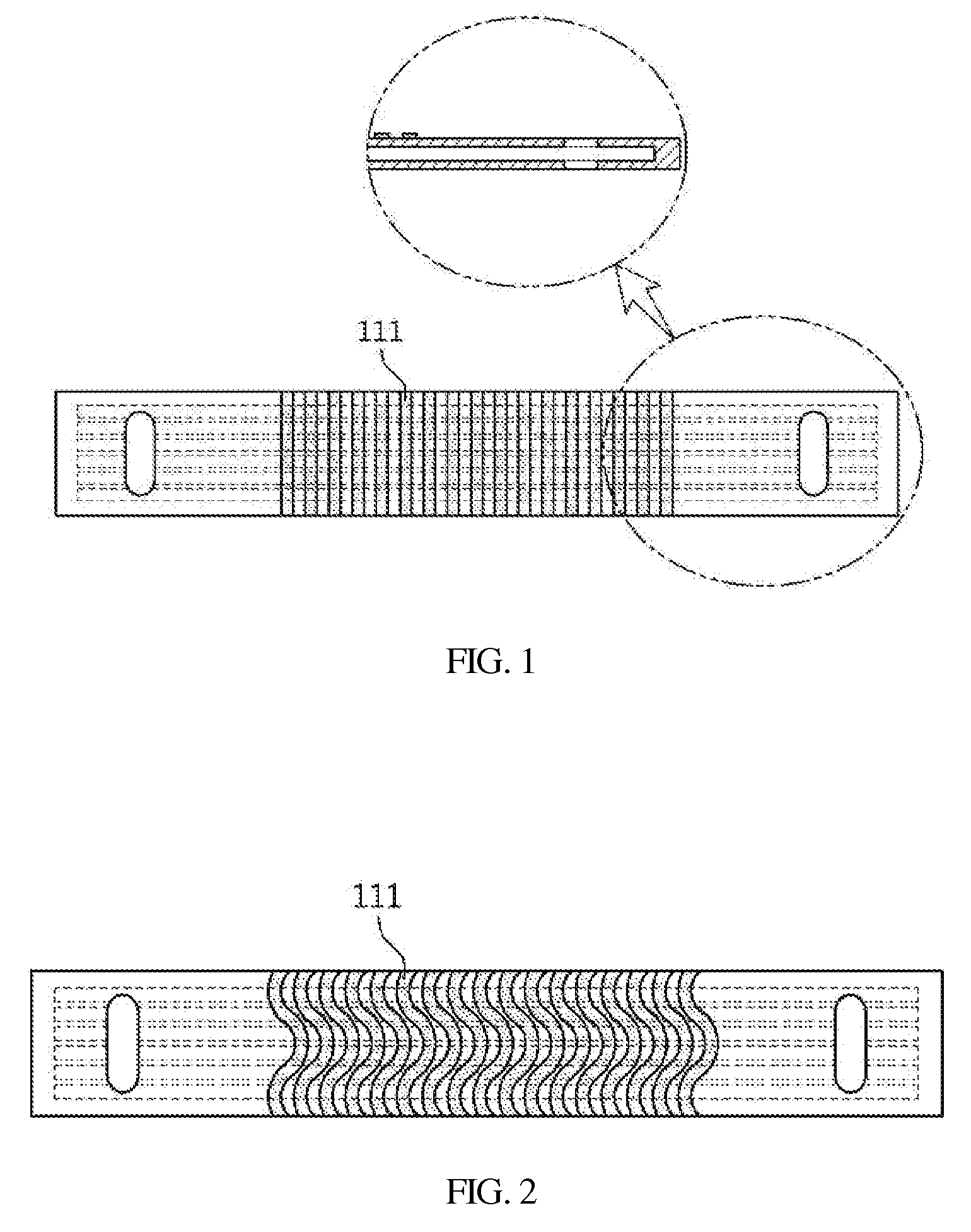
[0040]Using a ceramic extruder, an anode was formed so as to provide first gas passages therein, and both ends thereof were sealed. Subsequently, holes were formed in both ends of the dried body so that the first gas passages of unit cells were connected. As illustrated in FIG. 2, a connector 11 including a plurality of connection parts 111 spaced apart from each other and made of silicon carbide (SiC) was applied on the upper surface of the anode. As such, the connector may be manufactured using SiC bulk, SiC fiber composite, Crofer, Inconel, Ag, Au, Pt or perovskite ceramic (LSM, LSCF, etc.) tape, but the present invention is not limited thereto.

[0041]An electrolyte layer was applied on the surface of the anode not coated with the connector, after which heat treatment was performed at 1350˜1400° C. so that the connector and the electrolyte layer became dense. Subsequently, a cathode was applied o...

Example

EXAMPLE 3

Unit Cell for a Flat-Tubular Solid Oxide Fuel Cell or Solid Oxide Electrolyzer

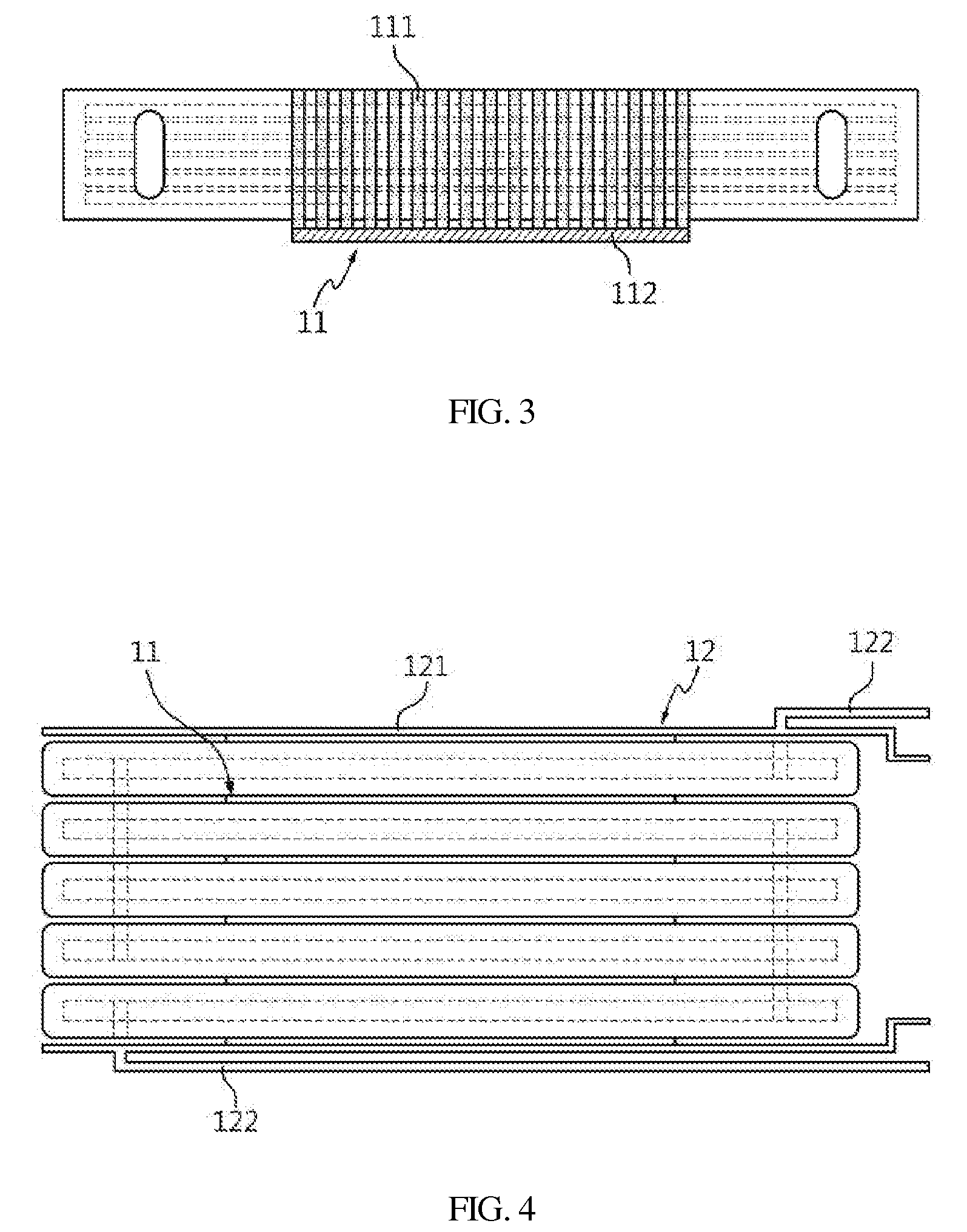
[0042]Using a ceramic extruder, an anode was formed so as to provide first gas passages therein, and both ends thereof were sealed. Subsequently, holes were formed in both ends of the dried body so that the first gas passages of unit cells were connected. As illustrated in FIG. 3, a connector 11 including a plurality of connection parts 111 and a support part 112 and made of silicon carbide (SiC) was applied on the lower surface of the anode. As such, the connector may be manufactured using SiC bulk, SiC fiber composite, Crofer, Inconel, Ag, Au, Pt or perovskite ceramic (LSM, LSCF, etc.) tape, but the present invention is not limited thereto.

[0043]The lateral surface of the connectors 111 to which the support part 112 was attached was provided to protrude from the outside of the unit cell along with the support part 112 so as to form a second gas passage. An electrolyte layer was applied on the su...


PUM


Abstract

This invention relates to a unit cell for a flat-tubular solid oxide fuel cell or solid oxide electrolyzer, and a flat-tubular solid oxide fuel cell and a flat-tubular solid oxide electrolyzer using the same, and more particularly to a unit cell for a flat-tubular solid oxide fuel cell or solid oxide electrolyzer, wherein the unit cell includes a connector including connection parts, thus decreasing the thickness of the unit cell and reducing the size of a cell stack, and to a flat-tubular solid oxide fuel cell and a flat-tubular solid oxide electrolyzer using the same.

Description

CROSS REFERENCE TO RELATED APPLICATION[0001]This application claims the benefit of Korean Patent Application No. KR 10-2012-0035884, filed Apr. 6, 2012, which is hereby incorporated by reference in its entirety into this application.BACKGROUND OF THE INVENTION[0002]1. Technical Field[0003]The present invention relates to a unit cell for a flat-tubular solid oxide fuel cell or solid oxide electrolyzer, and a flat-tubular solid oxide fuel cell and a flat-tubular solid oxide electrolyzer using the same.[0004]2. Description of the Related Art[0005]Typically, a fuel cell is a high-efficiency clean power generation technique which converts hydrogen contained in a hydrocarbon material such as natural gas, coal gas, methanol, etc., and oxygen in air into electrical energy via an electrochemical reaction. The fuel cell is classified into, depending on the kind of electrolyte used, an alkaline fuel cell, a phosphate fuel cell, a molten carbonate fuel cell, a solid oxide fuel cell, and a polym...

Claims


Application Information

Patent Timeline
IPC IPC(8): C25B1/04H01M8/04H01M50/77
CPCC25B1/04H01M8/04201Y02E60/521H01M8/243Y02E60/525C25B9/18H01M8/1213Y02E60/366Y02E60/36Y02P70/50Y02E60/50C25B9/70H01M8/12H01M8/02
Inventor KIM, SUN-DONGSEO, DOO-WONHAN, IN-SUBYU, JI-HAENGKIM, SE-YOUNGWOO, SANG-KUK
Owner KOREA INST OF ENERGY RES
Why Eureka
Try Eureka