Embedded electrooptical display

a technology of electrooptical display and embedded electrodes, which is applied in the direction of optics, instruments, non-linear optics, etc., can solve the problems of physical damage to the display, and achieve the effects of avoiding damage, preserving display flexibility, and fast and inexpensiv

Inactive Publication Date: 2013-10-24
KENT DISPLAY SYST
View PDF7 Cites 8 Cited by
  • Summary
  • Abstract
  • Description
  • Claims
  • Application Information

AI Technical Summary

Benefits of technology

[0003]Light curable flexible material that maintains display flexibility and avoids damage due to exposing the display to high temperatures and high pressure can be used for display ruggedization. Light curable materials are used in a method for embedding an electrooptical display in a protective (e.g., optically clear) durable layer that has many advantages. The method is fast, inexpensive, can embed electrooptical displays by molding in a batch process or in a roll-to-roll production process, and does not require high pressures or temperatures that are described in U.S. patent application Ser. Nos. 10 / 285,189 and 10 / 456,021. In U.S. Pat. No. 7,401,758 and U.S. patent application Ser. No. 12 / 758,026 is described an object with a display embedded into a top surface of the object. The display may have a durable layer on its front surface and light curable material layer on the back. In the present disclosure is described a method for embedding the flexible cholesteric reflective display (e.g., fully embedding from the front and back sides) into a skin-like protective optically clear layer of radiation curable resin. The method results in a stand alone display embedded into a durable layer of clear light curable resin. The method is compatible with a roll-to-roll manufacturing process.

Problems solved by technology

Forming an optically clear protective layer on the front of the device by an injection molding process requires high pressures and temperatures that often result in physical damage to the display, which is composed of flexible plastic substrates such as polyethylene terephthalate (PET), polycarbonate (PC), polyethylene naphthalate (PEN) or other plastic material, as well as heat sensitive liquid crystal material.

Method used


Image

  • Embedded electrooptical display
  • Embedded electrooptical display
  • Embedded electrooptical display

Examples


example 1

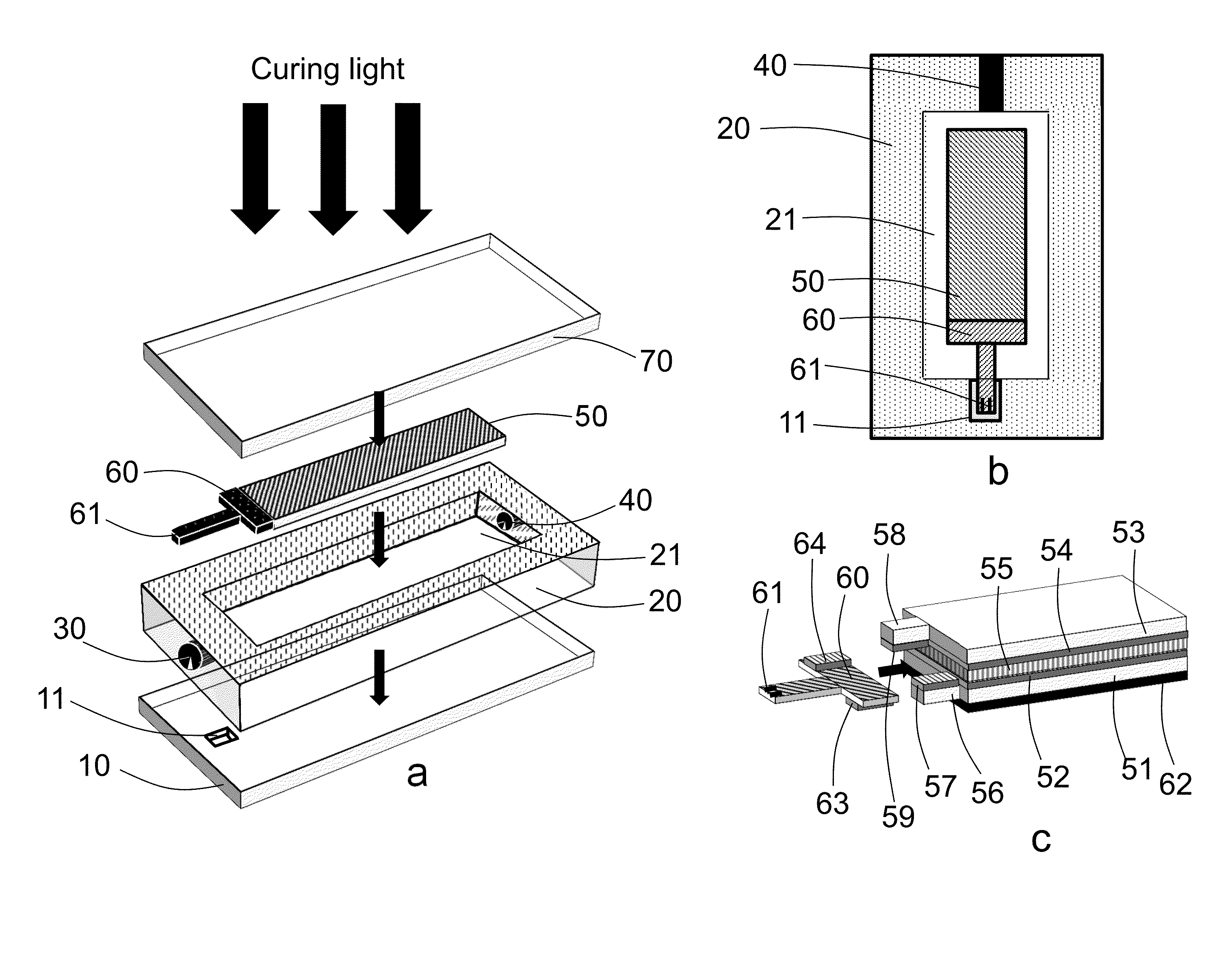
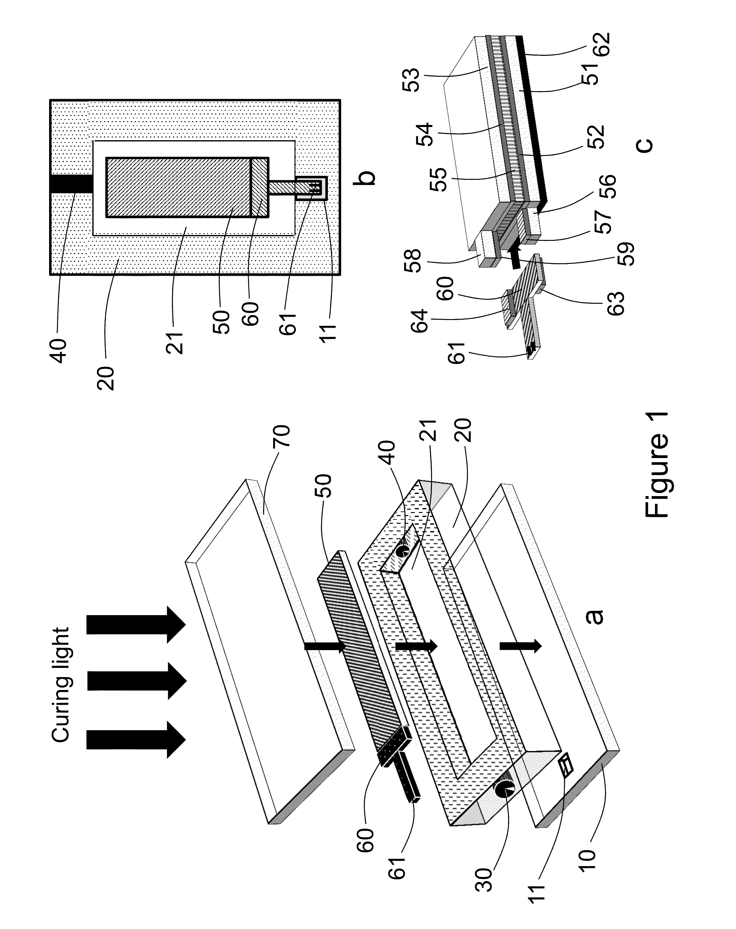
[0057]A reflective cholesteric liquid crystal display was made by forming a liquid crystal layer by a polymerization induced phase separation (PIPS) technique (U.S. Pat. No. 7,351,506) between two 2 mil PET substrates with conductive polymer layers on a roll-to-roll line. The individual display was placed into a mold, shown in FIG. 1, which was made from two part SortaClear 40 silicone mold material (Smooth-On, Inc.). The mold was filled with optically clear flexible visible light curable material Delo-Dualbond OC VE 512438 (Delo Industrial Adhesives LLC, Sudbury, Mass.) mainly composed of acrylate monomers and oligomers and cured with a Delolux 20 visible light source with peak wavelength 400 nm, 1 min cure time. The mold was designed to prevent flex circuit tab 61 from being covered with light curable material. After forming the optically clear casing (0.5 mm thick) on the front side, the mold was disassembled, the display was turned upside down and placed into a mold like in FIG....

example 2

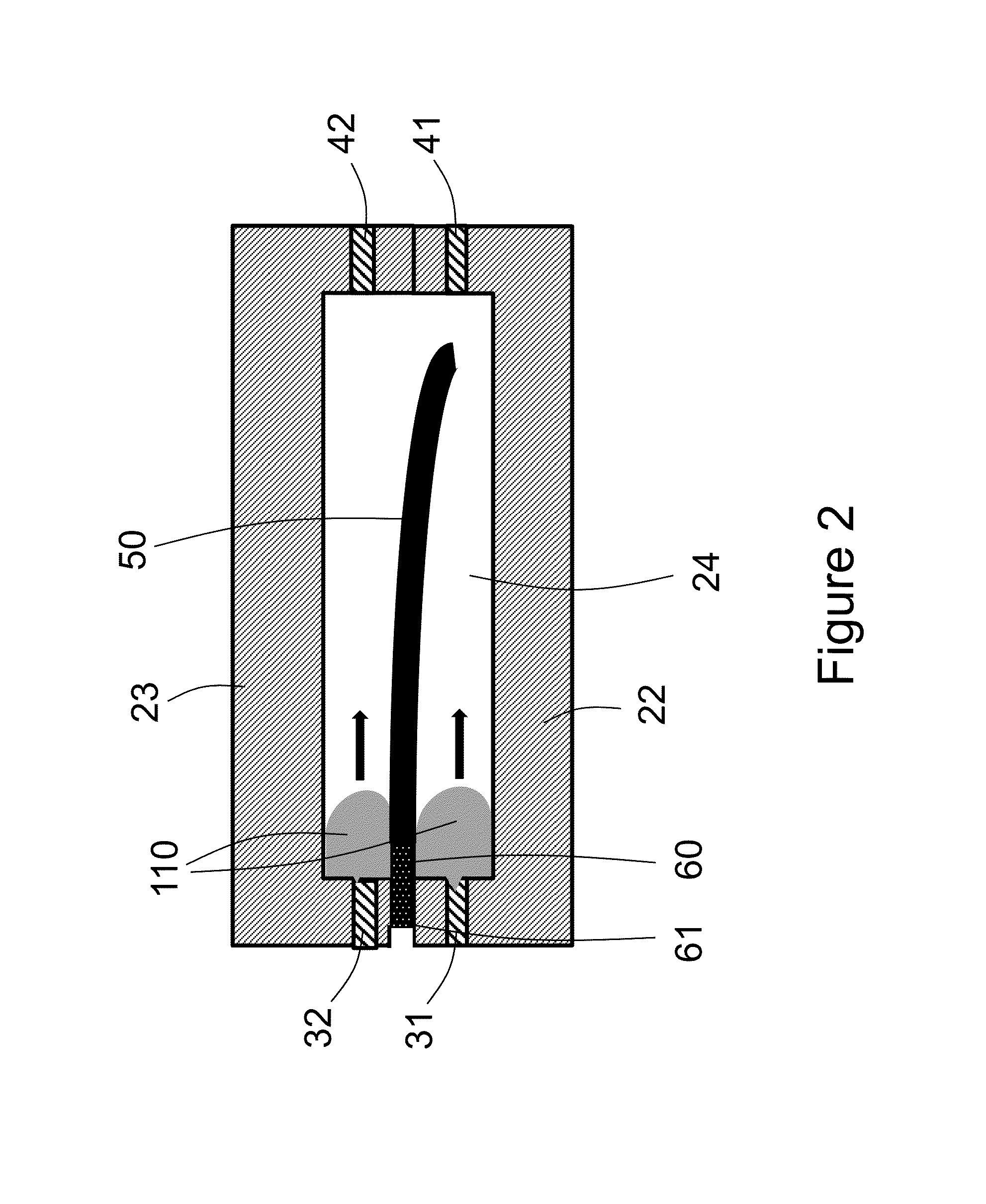
[0058]A reflective cholesteric liquid crystal display was made by forming the liquid crystal layer by the PIPS technique described in U.S. Pat. No. 7,351,506 between two 2 mil PET substrates with conductive polymer layers on a roll-to-roll line. The 0.5 mm thick shim 103 with a cavity larger than the display area was placed on the bottom substrate 102 as schematically shown in FIG. 3. The optically clear flexible visible light curable material 110 (Delo-Dualbond OC VE 512438 material from Delo Industrial Adhesives LLC, Sudbury, Mass.) mainly composed of acrylate monomers and oligomers was dispensed into the cavity formed by 103. The display 50 was placed on top of the light curable material 110. Then the 0.5 mm thick shim 104 with a cavity larger than display area was placed on top of 103 and optically clear flexible visible light curable material 110 (Delo-Dualbond OC VE 512438 from Delo Industrial Adhesives LLC) was dispensed into the cavity formed by 104 (on top of the display). ...

example 3

[0059]The optically clear protective casing in the shape of a protective skin-like case (about 1 mm thick) for a cell phone device or MP3 player was formed on the top of the reflective cholesteric liquid crystal displays in which the liquid crystal material made by a PIPS technique is disposed between two 2 mil PET substrates with conductive polymer layers on a roll-to-roll line. The individual display was placed into a mold made from two part SortaClear 40 silicone mold material (Smooth-On, Inc.) having a cavity in the shape of a protective case for a cell phone or MP3 player. The mold was filled with optically clear flexible visible light curable material Delo-Dualbond OC VE 512438 (Delo Industrial Adhesives LLC, Sudbury. MA) mainly composed of acrylate monomers and oligomers and cured with a Delolux 20 light source with peak wavelength 400 nm, 1 minute cure time from top and then another 1 minute cure time from the bottom part of the mold. After forming the case the mold was disa...


PUM

PropertyMeasurementUnit
thickaaaaaaaaaa
thickaaaaaaaaaa
peak wavelengthaaaaaaaaaa

Abstract

This disclosure features embedded electrooptical displays such as liquid crystal displays and methods of making the same. The displays are embedded in light curable material on one or both sides thereof. Processes for embedding the displays include injection molding and continuous roll-to-roll processing. The light curable material forms a protective covering over the display. Electrical interconnects connected to electrodes of the display can protrude from the protective layer. Once the display is embedded it can resist contact with moisture and mechanical damage. The protective layer can be clear or it can contain additives such as pigments or additives for UV protection. The embedded display with the protective layer may be molded into different shapes during the embedding process or thermoformed after the embedding process into different shapes. This permits the embedded display to be adapted into a variety of different electronic devices such as cell phones, smart phones, MP-3 players, a computer mouse, etc.

Description

FIELD OF THE INVENTION[0001]This disclosure pertains to an embedded electrooptical display and, in particular, to a liquid crystal display embedded in a light curable material.BACKGROUND OF THE INVENTION[0002]A reflective cholesteric liquid crystal display made from flexible substrates for various commercial applications often requires further ruggedization to prevent mechanical damage. The display device should be protected from abrasion, mechanical impact, pressure points, chemicals, and environmental factors such as UV light and moisture. A protective film can be attached by lamination to the front, or to the front and back, of the display with pressure sensitive adhesive (PSA), for example; however, the laminated display becomes rather rigid. Another approach to protect the display is through an injection molding process where a heat curable resin is formed on the front of the product as described in U.S. Pat. No. 5,993,588 and U.S. patent application Ser. No. 12 / 758,026. Formin...

Claims


Application Information

Patent Timeline
Patent Type & Authority Applications(United States)
IPC IPC(8): B29C35/08G02F1/13G02F1/1334
CPCB29C35/0805G02F1/1334G02F1/1313B29C35/0888B29C2035/0827G02F1/133308G02F1/133311
Inventor PISHNYAK, OLEGDEMIGLIO, ANDREWSCHNEIDER, TODDAVIS, DONALDBOWSER, MATHEWMONTBACH, ERICA
Owner KENT DISPLAY SYST
Why Eureka
Try Eureka