Heart assist device

a heart assist device and heart tube technology, applied in the field of heart assist devices, can solve the problems of affecting the ability of the heart tube to fully unload the ventricle, the risk of bleeding and/or thromboembolic complications, and the vads may also present a risk of complications, so as to reduce the size of the device, prevent the backflow into the ventricle, and enhance the natural flow of blood

Active Publication Date: 2013-10-31
HEART BIOTECH
View PDF20 Cites 2 Cited by
  • Summary
  • Abstract
  • Description
  • Claims
  • Application Information

AI Technical Summary

Benefits of technology

[0015]Embodiments of the present invention provide a failsafe mechanism providing an “open circuit” joined to the main aorta as the device does not restrict blood flow from the heart into the arterial system. They also reduce the complexity and number of components required in the device leading to a reduction in the size and cost of manufacture as well as a reduction in the number of potential points of failure.
[0029]Embodiments of the present invention provide that when the device is not configured to assist the heart on every beat, but with some reduced frequency, blood will still flow through the device without the action of the pump, allowing this natural blood flow to wash out the pump volume and providing a further mechanism for reducing the risk of thrombosis.

Problems solved by technology

They are considered capable of maintaining adequate circulation, although their capability to fully unload the ventricle is questionable.
Furthermore, the use of these pumps requires full anti-coagulation therapy coupled with antiplatelet medication and there is a risk of bleeding and / or thromboembolic complications partly caused by the very small clearance of the rotor inside the device.
However, such VADs may also present a risk of complications including thromboembolic complications.
Pulsatile devices do, however, have several disadvantages, such as their large size and complexity, which can increase the risk associated with insertion, predispose the patient to infection, and compress adjacent organs.
They may also contain many moving parts that can affect their durability.
Without this venting the displacement pumps would consume excessive power, as they would have to displace the pusher plates against a vacuum.
Whilst conventional LVADs can provide significant therapeutic benefits, they may also give rise to complications including infection, immunosuppression, clotting with resultant stroke, and bleeding secondary to anticoagulation.
By way of example, there is a high risk of the formation of blood clots within an LVAD in regions where blood flow is stagnant and this in turn requires the use of anticoagulation therapy in order to prevent thrombosis (clotting).
The use of anti-coagulants then leads to an increased risk of bleeding.
The design of existing commonly used VADs suffers from a number of other weaknesses.
The implantable devices are generally large (in the region of 120 cc in volume) and heavy and usually require open-heart surgery for implantation with the associated risks.
Their large size also prevents these devices from being placed within the chest cavity, due to lack of space, so that they are usually positioned in the stomach area, making it necessary to use a more powerful pump given the increased distance over which the blood is required to travel.
However, the risks associated with open heart surgery, as required to implant the existing LVADs, and with other complications is too great for those patients with less severe heart conditions.
In addition, the size of existing devices mean that they are only suitable for use in patients weighing more than around 70 kg, preventing their use in small adults or children.
However this method poses a potentially significant risk of damage to the tissue of the aorta and histological changes have been observed in the outer wall of the aorta during animal and early clinical trials of such a device.

Method used


Image

  • Heart assist device
  • Heart assist device
  • Heart assist device

Examples


Embodiment Construction

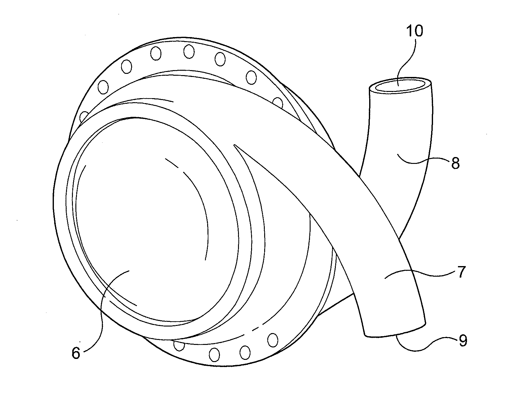
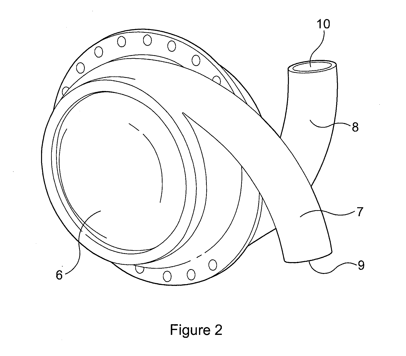
[0037]FIG. 2 shows a LVAD comprising left and right side plates secured together with an airtight seal to form a generally hollow cylindrical housing 6. Each of the side plates is connected to or formed integrally with a curved hollow tube 7, 8. When the side plates are secured together the tubes 7, 8 open into the hollow interior of the housing at substantially diametrically opposed locations, entering the housing with a curvature that follows that of the curved interior surface of the housing. The ends of the tubes remote from the housing, referred to hereinafter as the “descending port”9 and “ascending port”10, face in substantially opposite directions. Neither the tubes 7,8 nor the housing 6 are provided with valves.

[0038]The side plates forming the housing, and the tubes, are made from a durable, biocompatible material such as titanium or moulded polyurethane. The hollow interior of the housing can have a volume in the region of 60 cc to 80 cc and the internal diameter of the t...


PUM


Abstract

A ventricular assist device comprising a housing defining an interior space, at least two ports opening into said interior space, and at least one pump for pumping blood between the ports through said interior space, the ports and interior space providing a continuous blood flow path that is not interrupted by valves.

Description

CROSS-REFERENCE TO RELATED APPLICATIONS[0001]This application is a continuation of U.S. application Ser. No. 12 / 934,300, filed on Dec. 2, 2010, which claims the priority of PCT / GB2008 / 050217, filed on Mar. 26, 2008, the entire contents of which is hereby incorporated in total by reference.FIELD OF THE INVENTION[0002]The present invention relates to a heart assist device and more particularly, though not necessarily, to an improved implantable left ventricular assist device.BACKGROUND TO THE INVENTION[0003]A ventricular assist device, or VAD, is a mechanical device used to help either one or both ventricles of the heart to pump blood. VADs are designed to assist either the right (RVAD) or left (LVAD) ventricle, or both at once (BVAD). The choice of device depends on the underlying heart condition, although LVADs are the most widely used.[0004]In early procedures, the VAD pump was placed outside the body. More recently, the most commonly used VADs comprise an integrated pump and are i...

Claims


Application Information

Patent Timeline
Patent Type & Authority Applications(United States)
IPC IPC(8): A61M1/10
CPCA61M1/1053A61M1/107A61M1/122A61M1/1037A61M1/1086A61M60/898A61M60/274A61M60/148A61M60/268A61M60/178A61M60/515A61M60/454A61M60/861
Inventor THOMPSON, RAYMONDYACOUB, MAGDI HABIB
Owner HEART BIOTECH
Why Eureka
Try Eureka