Automatic Fat Removal Device

a fat removal device and automatic technology, applied in the field of fat removal devices, can solve the problems of increasing the workload of surgeons, and increasing the time of ultrasonic fat removal devices, so as to reduce the load of surgeons and improve the cost effectiveness and surgical outcomes.

Active Publication Date: 2013-10-31
CHENG MING HUEI
View PDF30 Cites 3 Cited by
  • Summary
  • Abstract
  • Description
  • Claims
  • Application Information

AI Technical Summary

Benefits of technology

[0012]An object of the present invention is to provide an automatic fat removal device, wherein a navigation system and a hollow suction tube are employed to replace the conventional rigid suction tube to perform a 3-dimensional liposuction process in the adipose layer thereby improving cost effectiveness and surgical outcome.
[0013]Another object of the present invention is to provide an automatic fat removal device, which employs a robotic arm to replace manual effort of the surgeon during surgery to decrease the load of the surgeon.

Problems solved by technology

Furthermore, dermal-fat excision, which directly excise extracts out the excess undesirable fat through a dermal incision, may cause scars, seroma, hematoma and infection.
However, such ultrasonic fat removal device takes more time and the probe temperature may be raised with the increased energy for fat disintegration.
However, a conventional liposuction device is operated at a single fixed point each time, and there is a variation in depth between each two liposuctions, and thus unevenness of skin development rise if the suction tube is too close to the skin.
Also, a reciprocating liposuction movement needed during a typical massive liposuction surgery is performed by a surgeon, and a considerable physical strength is required, resulting fatigue of the surgeon, which may cause more complications.

Method used


Image

  • Automatic Fat Removal Device
  • Automatic Fat Removal Device
  • Automatic Fat Removal Device

Examples


embodiment 1

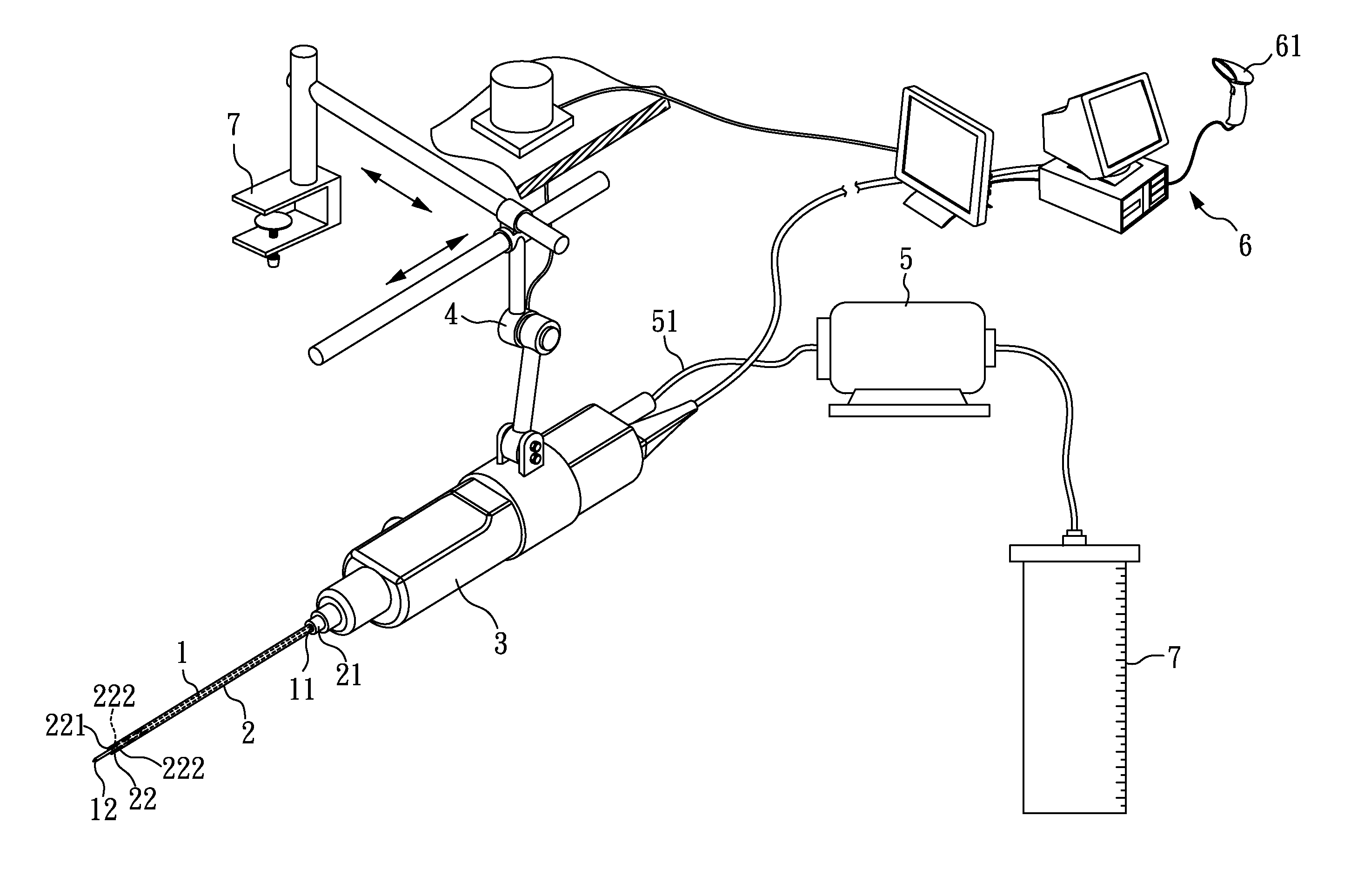
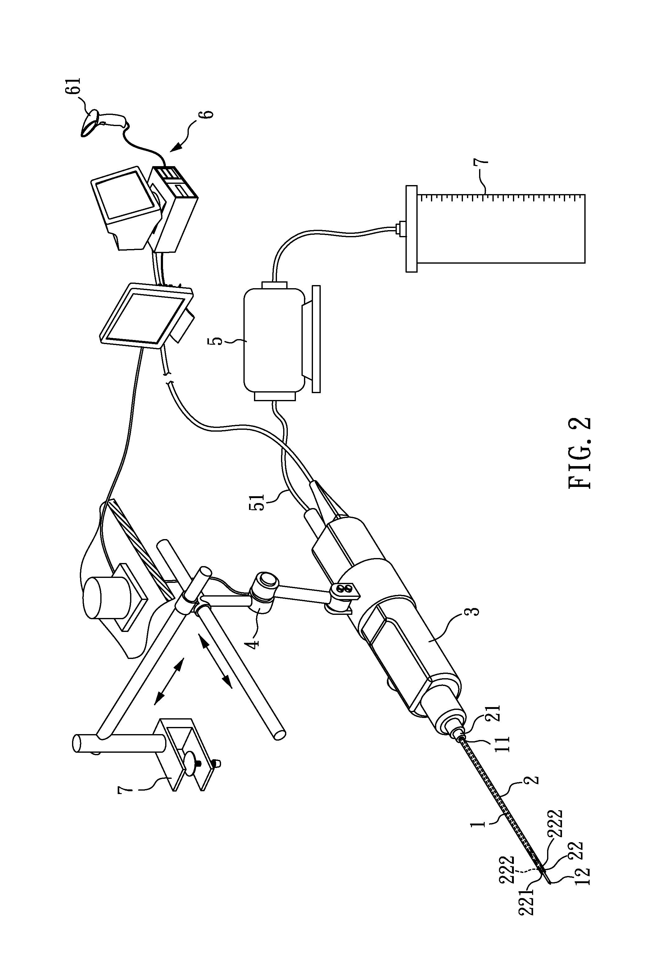
[0035]Referring to FIG. 2, which shows a schematic view of the automatic fat removal device according to Embodiment 1 of the present invention. The automatic fat removal device of the present invention comprises a navigation system 1, a hollow suction tube 2, a connection unit 3, a robotic arm 4 with 2-dimensional movement, and one operation table fixation 7, a suction unit 5, a microprocessor 6, and a power supply unit (not shown), wherein the navigation system 1 has a first connection end 11 and a first terminal 12, and the hollow suction tube 2 has a second connection end 21 and a second terminal 22. In addition, the navigation system 1 is disposed inside the hollow suction tube, and the connection unit 3 is connected to the first connection end 11 of the navigation system 1 and the second connection end 21 of the hollow suction tube 2. As such, the navigation system 1 and the hollow suction tube 2 can be affixed to the connection unit 3 which may serve as a holder component. The...

embodiment 2

[0041]Referring to FIG. 4, which shows a schematic view of the fat removal module according to Embodiment 2 of the present invention. The fat removal module of the present invention comprises a navigation system 1, a hollow suction tube 2, and a connection unit 3, wherein the navigation system 1 has a first connection end 11 and a first terminal 12, and the hollow suction tube 2 has a second connection end 21 and a second terminal 22. In addition, the navigation system 1 is disposed inside the hollow suction tube, and the connection unit 3 is connected to the first connection end 11 of the navigation system 1 and the second connection end 21 of the hollow suction tube 2.

[0042]First, the navigation system 1 is inserted into a predetermined liposuction incision, and then the navigation system 1 is manipulated by a push-button navigation system adjusting element 31 to guild the processing route and direction in the adipose layer. Next, the hollow suction tube 2 is manipulated by a push...

embodiment 3

[0045]Referring to FIG. 5, which shows a schematic view of the fat removal module according to Embodiment 3 of the present invention. The fat removal module of the present Embodiment is approximately the same as Embodiment 2 except that the suction unit 5 connected to the connection unit 3 is a pump. Thus, the switch of the suction unit 5 is controlled in a form of push-button by a suction unit controlling element 53 installed on the connection unit 3 to adjust the rate of the suction unit 5. The suction unit controlling element 53 is a combination of push-buttons comprising a switch button, an acceleration button, and a deceleration button, and is electrically connection to the suction unit 5. In addition, the connection unit 3 of the present Embodiment is connected to a wire 30 extending to a power supply unit (not shown) to provide the electric power source of the present Embodiment.

[0046]In this Embodiment, the liposuction process is performed in a semi-automatic manner, and the...


PUM


Abstract

The present invention relates to a fat removal device, which comprises: a navigation system having a first connection end and a first terminal; a hollow suction tube having a second connection end and a second terminal, wherein the navigation system is disposed inside the hollow suction tube; a connection unit connected to the first connection end and the second connection end; a robotic arm connected to the connection unit to rotate and move the connection unit multidirectionally; a suction unit connected to the connection unit by a pipeline between the connection unit and the suction unit; and a microprocessor connected to the connection unit, the robotic arm, and the suction unit, to transmit signals from one to another.

Description

CROSS REFERENCE TO RELATED APPLICATION[0001]This application claims the benefits of the Taiwan Patent Application Serial Number 101115157, filed on Apr. 27, 2012, the subject matter of which is incorporated herein by reference.BACKGROUND OF THE INVENTION[0002]1. Field of the Invention[0003]The present invention relates to a fat removal device, and particularly to an automatic fat removal device which comprises a navigation system, a hollow suction tube, a connection unit, a robotic arm, a suction unit, and a microprocessor.[0004]2. Description of Related Art[0005]A typical method of fat removal surgery includes high frequency current fat disintegration, dermal-fat excision, ultrasonic fat disintegration, mechanical vibration, negative pressure suction, and so on.[0006]Furthermore, dermal-fat excision, which directly excise extracts out the excess undesirable fat through a dermal incision, may cause scars, seroma, hematoma and infection.[0007]Ultrasonic assisted fat removal device, f...

Claims


Application Information

Patent Timeline
Patent Type & Authority Applications(United States)
IPC IPC(8): A61M1/00A61B19/00
CPCA61M1/008A61B19/2203A61M2202/08A61B34/32A61B2090/373A61B2034/301A61B34/30A61B34/76A61M1/84A61B17/320068A61M1/89A61B5/150816A61B17/3403A61B2017/003A61B34/70
Inventor CHENG, MING-HUEI
Owner CHENG MING HUEI
Why Eureka
Try Eureka