
Conformal low temperature hermetic dielectric diffusion barriers

a dielectric diffusion barrier and low temperature technology, applied in the field of semiconductor devices, can solve the problems of increasing interconnect capacitance, causing voids and/or defects, and difficult electrical isolation

Active Publication Date: 2013-11-07
INTEL CORP
View PDF20 Cites 51 Cited by
  • Summary
  • Abstract
  • Description
  • Claims
  • Application Information

AI Technical Summary

Benefits of technology

The present invention relates to a method for forming a dielectric diffusion barrier in semiconductor devices, which can provide a more effective seal to prevent metal diffusion and moisture infiltration. The method involves depositing a low-k film using PECVD or LPCVD techniques and then performing a plasma treatment to improve conformality and step coverage. The invention also provides materials and techniques to reduce the minimum thickness of the dielectric diffusion barrier. The method can be used to fabricate ICs with improved reliability and performance.

Problems solved by technology

As transistor density and non-planarity increases, so too does the interconnect metallization, increasing interconnect capacitance and making electrical isolation more difficult.
Also, topography present due to radical 3D structures may induce voids and / or defects that need to be sealed / covered by a conformal dielectric layer.
Plasma enhanced chemical vapor deposition (PECVD) processes are typically used for dielectric deposition in low-k interconnect applications but do not offer high conformality / step coverage.
Due to difficulties in achieving perfect coverage and film densification over 3D topography, there is therefore a minimum thickness requirement for a dielectric diffusion barrier.

Method used


Image

  • Conformal low temperature hermetic dielectric diffusion barriers
  • Conformal low temperature hermetic dielectric diffusion barriers
  • Conformal low temperature hermetic dielectric diffusion barriers

Examples


Embodiment Construction

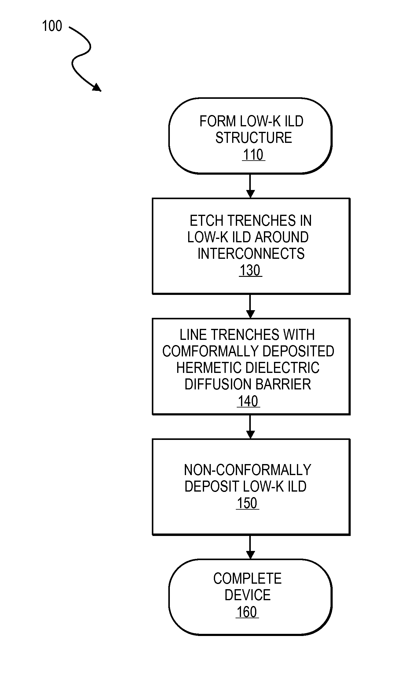
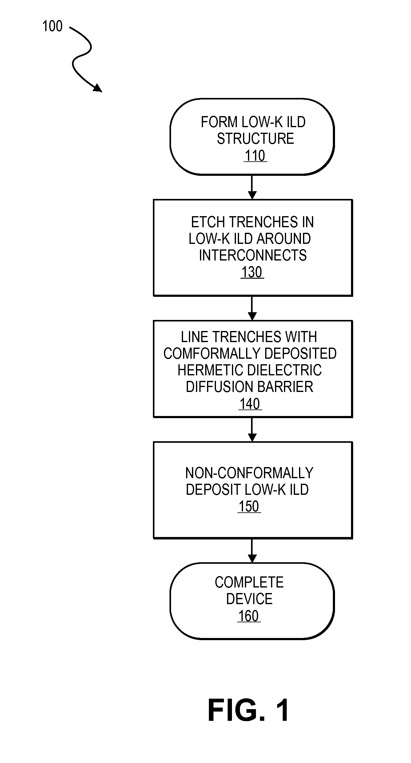
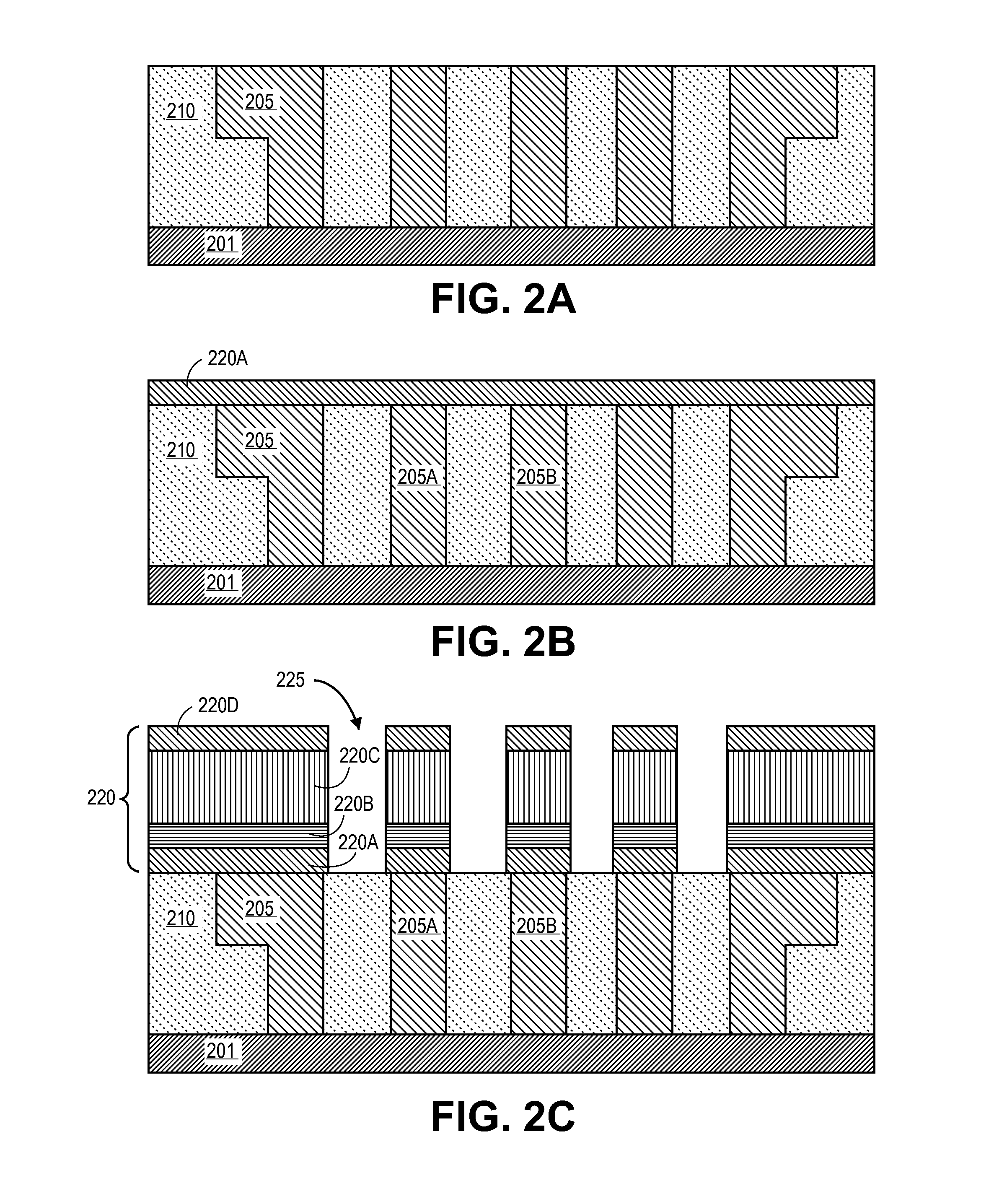
[0011]In the following description, numerous details are set forth, however, it will be apparent to one skilled in the art, that the present invention may be practiced without these specific details. In some instances, well-known methods and devices are shown in block diagram form, rather than in detail, to avoid obscuring the present invention. Reference throughout this specification to “an embodiment” means that a particular feature, structure, function, or characteristic described in connection with the embodiment is included in at least one embodiment of the invention. Thus, the appearances of the phrase “in an embodiment” in various places throughout this specification are not necessarily referring to the same embodiment of the invention. Furthermore, the particular features, structures, functions, or characteristics may be combined in any suitable manner in one or more embodiments. For example, a first embodiment may be combined with a second embodiment anywhere the two embodi...


PUM

PropertyMeasurementUnit
dielectric constantaaaaaaaaaa
thicknessaaaaaaaaaa
thicknessaaaaaaaaaa

Abstract

Conformal hermetic dielectric films suitable as dielectric diffusion barriers over 3D topography. In embodiments, the dielectric diffusion barrier includes a dielectric layer, such as a metal oxide, which can be deposited by atomic layer deposition (ALD) techniques with a conformality and density greater than can be achieved in a conventional silicon dioxide-based film deposited by a PECVD process for a thinner contiguous hermetic diffusion barrier. In further embodiments, the diffusion barrier is a multi-layered film including a high-k dielectric layer and a low-k or intermediate-k dielectric layer (e.g., a bi-layer) to reduce the dielectric constant of the diffusion barrier. In other embodiments a silicate of a high-k dielectric layer (e.g., a metal silicate) is formed to lower the k-value of the diffusion barrier by adjusting the silicon content of the silicate while maintaining high film conformality and density.

Description

TECHNICAL FIELD[0001]Embodiments of the present invention generally relate to semiconductor devices, and more particularly to conformal dielectric diffusion barriers.BACKGROUND[0002]Microelectronic devices, such as integrated circuits incorporating metal-oxide-semiconductor transistors (MOSFETs), or the like, continue to scale by reducing pitches between adjacent features and incorporating three-dimensional transistor structures (e.g., finFETs). As transistor density and non-planarity increases, so too does the interconnect metallization, increasing interconnect capacitance and making electrical isolation more difficult. Interconnect processes over the last decade have increasingly incorporated “low-k” films (e.g., those below ˜3.2) as the material of choice of inter-level dielectrics (ILDs), some further implementing air gap formation whereby voids in the ILD between adjacent metal lines are deliberately introduced. Also, topography present due to radical 3D structures may induce v...

Claims


Application Information

Patent Timeline
Patent Type & Authority Applications(United States)
IPC IPC(8): H01L21/768H01L23/522
CPCH01L21/76802H01L23/522H01L21/02178H01L21/022H01L21/0228H01L21/7682H01L21/76829H01L23/5222H01L23/53295H01L2924/0002H01L2924/00H01L21/02304H01L21/76831H01L21/76877H01L23/5226H01L23/53228H01L23/564
Inventor KING, SEANYOO, HUI JAEKOSARAJU, SREENIVASGLASSMAN, TIMOTHY
Owner INTEL CORP
Learn More