Contactless power transfer system

a technology of power transfer system and contactless connection, which is applied in the direction of electric devices, rail devices, hybrid vehicles, etc., to achieve the effects of good connectivity with commercial power supply, increased total power feeding efficiency, and reduced cos

Inactive Publication Date: 2013-11-07
TECHNOVA +1
View PDF6 Cites 66 Cited by
  • Summary
  • Abstract
  • Description
  • Claims
  • Application Information

AI Technical Summary

Benefits of technology

[0039]According to the contactless power transfer system of the present invention, the total power feeding efficiency may be increased as compared with the conventional system. Further, the cost may be reduced. Furthermore, the high power factor boost rectifier is used so that the harmonic wave is not generated and the connectivity with the commercial power supply is good. The voltage is easily controlled when the secondary-side secondary battery is charged.

Problems solved by technology

However, due to misalignment of the power transmission coil and the power reception coil in a horizontal direction or variation in a gap length in a vertical direction, a coupling factor between the power transmission coil and the power reception coil varies.

Method used


Image

  • Contactless power transfer system
  • Contactless power transfer system
  • Contactless power transfer system

Examples


first exemplary embodiment

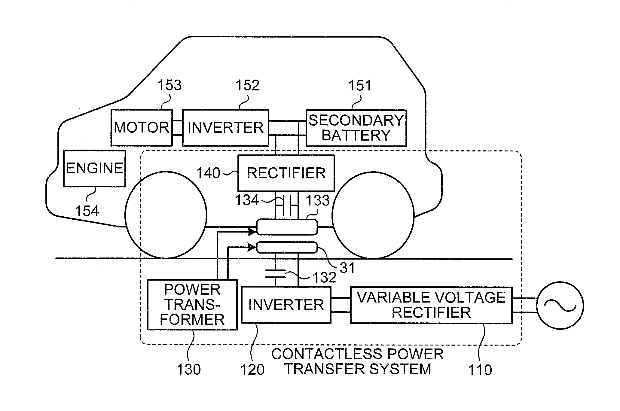
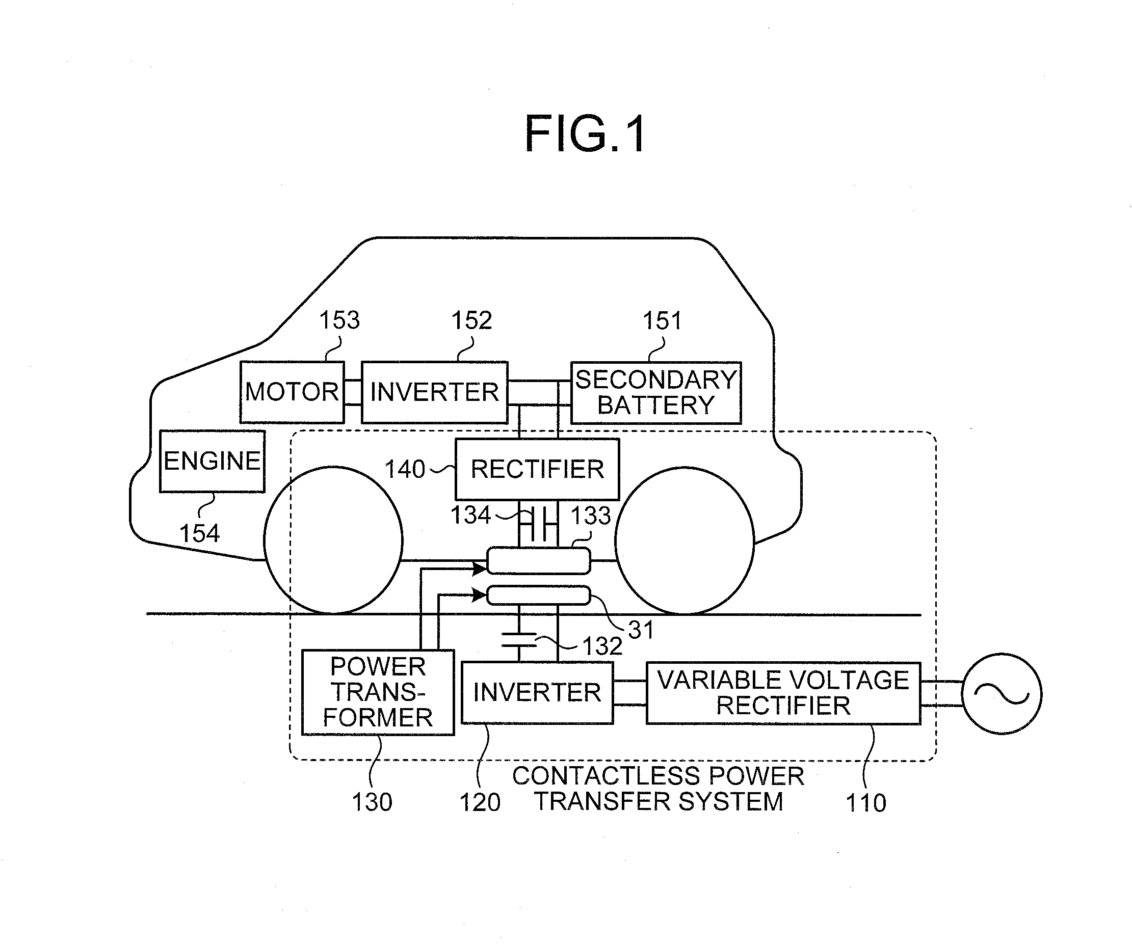
[0054]FIG. 1 schematically illustrates an example when a contactless power transfer system according to the present invention is used to charge a plug-in hybrid vehicle.

[0055]The plug-in hybrid vehicle which is charged has an engine 154 and a motor 153 mounted as a driving source and includes a secondary battery 151 which is a power supply for the motor and an inverter 152 which converts a direct current of the secondary battery into an alternating current to supply the alternating current to the motor.

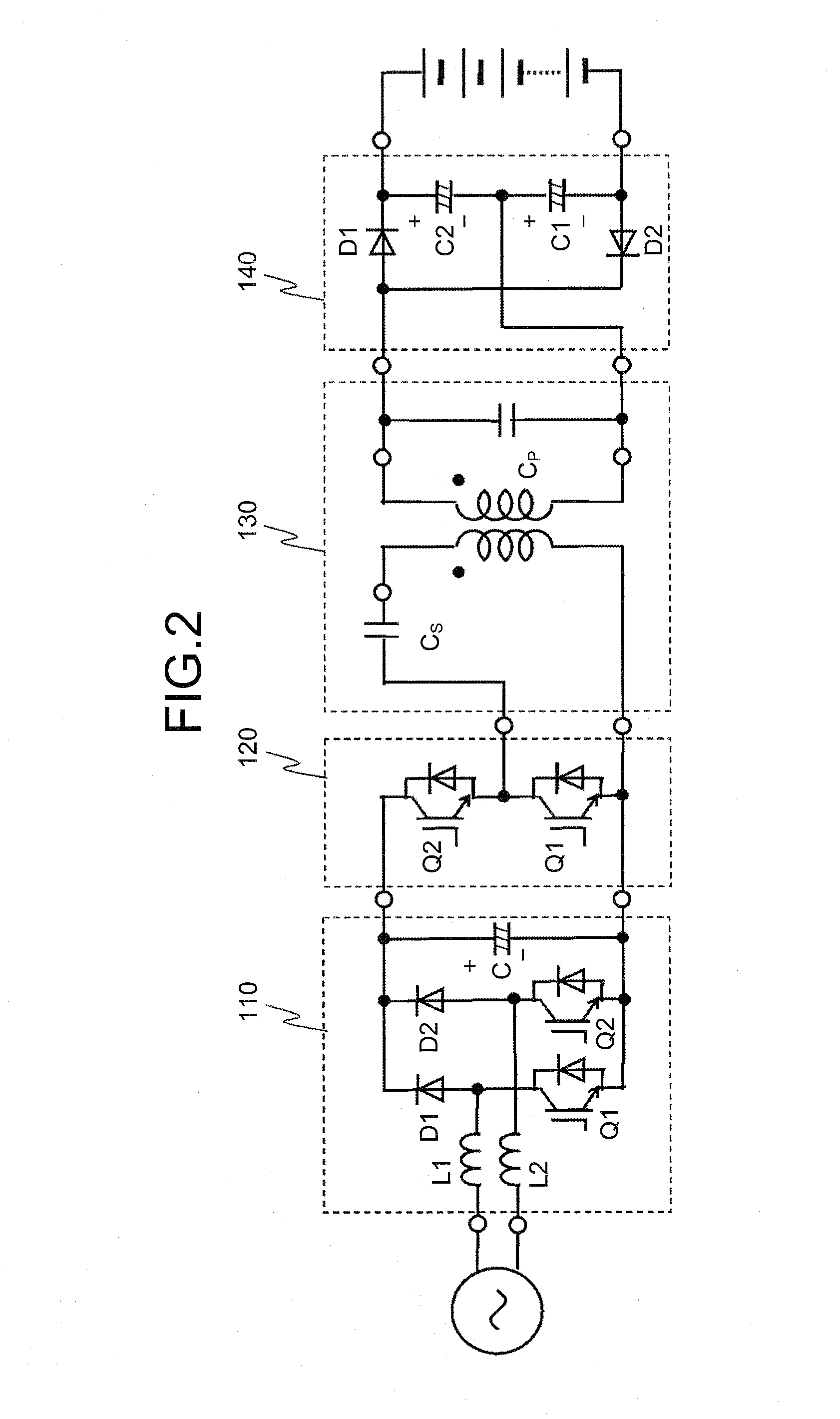
[0056]The contactless power transfer system which feeds the secondary battery 151 with power includes a variable voltage rectifier 110 which converts an alternating current of the commercial power supply into a direct current and varies a voltage thereof, an inverter 120 which generates a high frequency alternating current from the direct current, a power transmission coil 131 which is one of a contactless power transformer 130, and a serial capacitor 132 which is connected with the p...

second exemplary embodiment

[0095]In the second exemplary embodiment, a vehicle driving device which receives power using the contactless power transfer system of the first exemplary embodiment will be described.

[0096]FIG. 11 schematically illustrates the vehicle driving device.

[0097]A vehicle 100 includes a battery 40 which is charged by the contactless power transfer system, a voltage sensor 71 which detects a voltage of the battery 40, a current sensor 72 which detects a current of the battery 40, a BMS (Battery Management System) 75 which monitors a charging status of the battery 40, a vehicle driving device 10B which drives a rotary electricity (motor generator MG) by the power of the battery 40, a cut-off circuit 30 which is interposed between the battery 40 and the vehicle driving device 10B, a power reception coil 73 which receives the power from a power transmission coil 85 of a ground-side device 200 of the contactless power transfer system, a capacitor 74 which is connected in parallel to the power ...


PUM

PropertyMeasurementUnit
output voltageaaaaaaaaaa
frequencyaaaaaaaaaa
output voltageaaaaaaaaaa

Abstract

A half-bridge inverter is used for a high frequency alternating current power supply to be connected to a primary side of a contactless power transformer, and a voltage-doubler rectifier is used to convert a secondary-side alternating current output of the contactless power transformer into a direct current.

Description

TECHNICAL FIELD[0001]The present invention relates to a contactless power transfer system which contactlessly feeds a moving body such as an electric vehicle with power and has an object to improve a total efficiency during the power feeding.BACKGROUND ART[0002]A contactless power transfer device uses electromagnetic induction between a primary coil (power transmission coil) and a secondary coil (power reception coil) to supply power from the power transmission coil to the power reception coil. The contactless power transfer device may be used to charge a secondary battery which is mounted in an electric vehicle or a plug-in hybrid vehicle and it is expected that a demand for a contactless power transfer device for charging a vehicle will be increased in the near future.[0003]In the case of a contactless power transfer device for charging a vehicle, a vehicle with a power reception coil mounted on a bottom surface of a floorboard comes to a stop at a position where the power recepti...

Claims


Application Information

Patent Timeline
Patent Type & Authority Applications(United States)
IPC IPC(8): B60L11/18H02J7/02H01F38/14B60L50/15B60L50/16H02M1/00
CPCB60L11/182H01F38/14H02J7/025B60L2210/10B60L2210/30B60L2210/40B60L2220/54H02M7/217Y02T90/12Y02T90/14B60M7/003B60L15/007Y02T10/7072B60L50/61B60L50/16B60L50/51B60L53/24B60L53/36B60L53/122H02J2310/48Y02T10/62Y02T10/64Y02T10/70Y02T10/72H02J50/12H02M1/007H02M3/33571H02J50/10B60L53/12
Inventor ABE, SHIGERUYASUDA, TOMIOYAMANOUCHI, RYOUICHISUZUKI, AKIRA
Owner TECHNOVA
Why Eureka
Try Eureka