Automated system for sample preparation and analysis

a sample preparation and analysis technology, applied in the field of sample preparation systems and sample analysis systems, can solve the problems of sophisticated lcms specialist technologists, and not being well suited to the typical hospital clinical lab or medical lab technician. , to achieve the effect of significantly increasing the “time to result” for each specimen

Active Publication Date: 2013-11-07
THERMO FISCHER SCI OY
View PDF5 Cites 87 Cited by
  • Summary
  • Abstract
  • Description
  • Claims
  • Application Information

AI Technical Summary

Benefits of technology

[0009]The present invention overcomes the foregoing problems and other shortcomings, drawbacks, and challenges of conventional sample preparation and sample analysis systems. While the invention will be described in connection with certain embodiments, it will be understood that the invention is not limited to these embodiments. To the contrary, this invention includes all alternatives, modifications, and equivalents as may be included within the spirit and scope of the present invention.

Problems solved by technology

However, the instrumentation required for LCMS is technically complex and not well suited to the typical hospital clinical lab or medical lab technician.
Such complicated equipment and sophisticated scientific techniques require very sophisticated LCMS specialist technologists, and heretofore only the large centrally located reference laboratories have been able to use such LCMS equipment for clinical diagnostics.
While this batch mode automation approach may reduce the amount of LCMS technologist intervention, it significantly increases the “time to result” for each specimen.
Thus, non-urgent specimens may not be processed for several hours or even days prior to analysis.
For time sensitive specimens, for example, for emergency department patients or transplant patients requiring short turnaround time results for immediate treatment decisions, such delays are unacceptable.
Still further, some specimens have a limited shelf-life due to deterioration of one or more analytes or evaporation which distorts the concentration of the analyte.
Therefore, there is a set of complex factors that determine how long a specimen of a particular type may be delayed behind other specimens of a higher priority.
As such, it is often impractical for a hospital lab to purchase multiple systems for different dedicated analyses.
Thus, it is impractical for a hospital, even a large one, to use batch mode automation for clinical LCMS application, as it does not have the scale of a central reference laboratory and may be forced to make frequent changes to the LCMS hardware and complex setting, as it switches the testing from one type or class of analytes to another.
Faced with the large economic and technical challenges, such clinical labs have been unable to reap the technical benefit of LCMS technologies for routine patient specimens, but have been forced to send patient samples on to the central reference labs.

Method used


Image

  • Automated system for sample preparation and analysis
  • Automated system for sample preparation and analysis
  • Automated system for sample preparation and analysis

Examples


example 1

[0332]Turning now to FIG. 39A, five chromatograms 1200, 1202, 1204, 1206, 1208 corresponding to each of five analytes contained within a second sample are schematically shown as would be detected on a LC-MS system. A chromatogram is a graphical representation of the time dependent total ion count (“TIC”) for each analyte of interest measured at the ion detector 150 (FIG. 4B). Accordingly, the chromatogram includes retention time along the x-axis, TIC along the y-axis, and m / z along the z-axis. In the particular example, the first, second, and third chromatograms 1200, 1202, 1204 correspond to first, second, and third analytes that elute substantially simultaneously off of the columns 114, 116 (FIG. 7A) during a first elution window. The fourth and fifth chromatograms 1206, 1208 correspond to fourth and fifth analytes, respectively, which elute at later times (second and third elution windows, respectively).

[0333]The LC-MS system is capable of scanning at a rate that ranges from 2000...

example 2

[0338]FIG. 40 illustrates TIC for all m / z values measured, in toto, at the ion detector 150 (FIG. 4B) of the mass spectrometer 120 (FIG. 4B) for a plurality of prepared samples, ad infinitum, where the prepared samples undergo a multiplexing protocol and are scheduled as described in detail previously. The peaks represent one or more gas phase ions corresponding to one or more analytes eluting off of the columns 114, 116 (FIG. 7A). In this way, and as clearly demonstrated in this figure, the resources of the mass spectrometer 120 (FIG. 4B) are maximized as compared to conventional methodologies where one sample must completely elute from a column 114, 116 (FIG. 7A) and be analyzed before a second sample may be injected into the column 114, 116 (FIG. 7A) for analysis.

[0339]As also shown in FIG. 40, each time a new sample is injected into the columns 114, 116 (FIG. 7A), a signal may be generated to indicate a zeroing of the retention time window and the start of a new analysis. The si...


PUM


Abstract

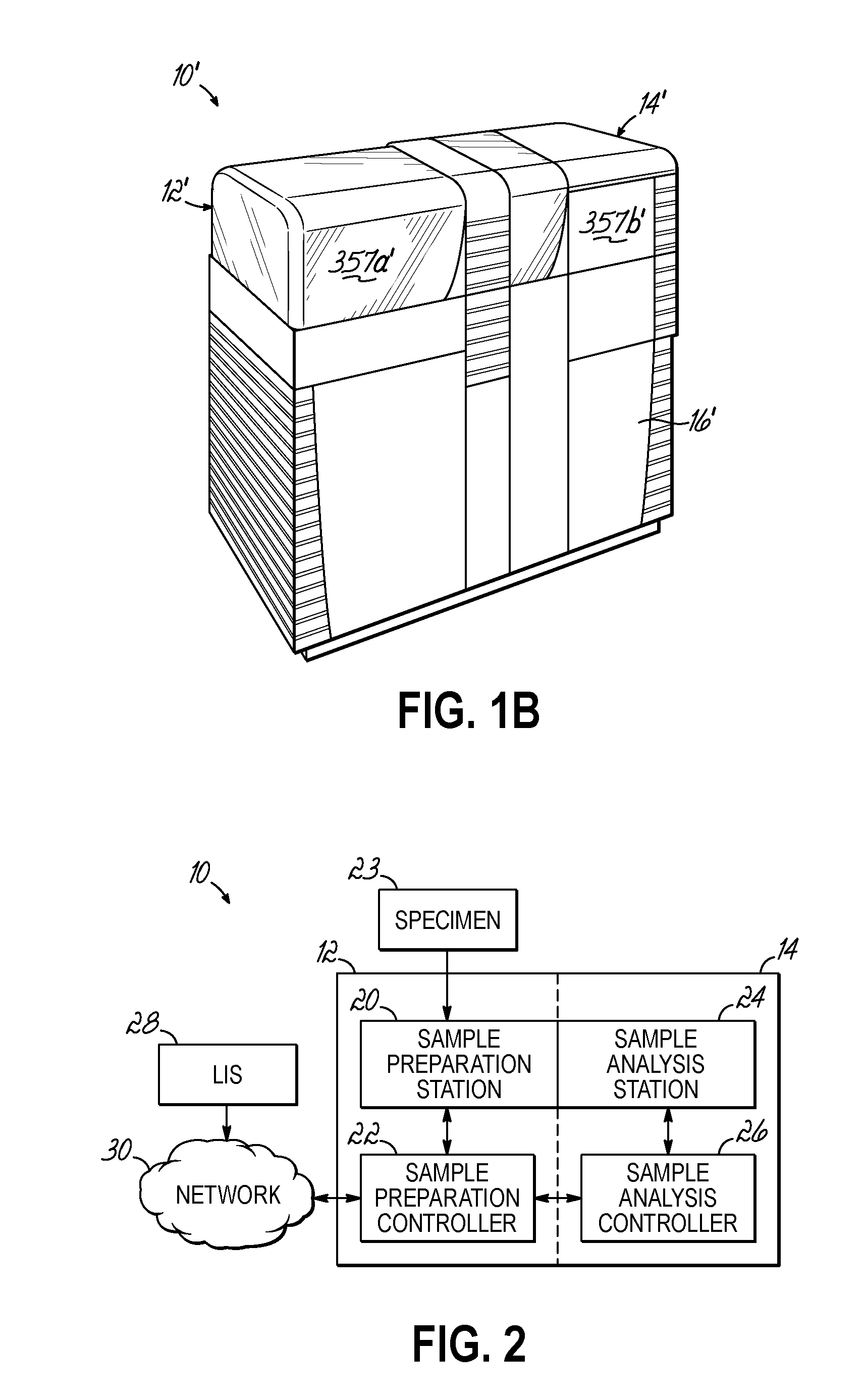
A sample preparation and analysis system. The system 10 includes a sample preparation system 12 and a sample analysis system 14. The sample preparation system 12 prepares samples in accordance with an assay that is selected from a database containing a plurality of unique assays. The sample analysis system 14 includes an analyzer 110 that is dynamically reconfigurable based on the selected assay so as to analyze the prepared sample in accordance with that selected assay. A data communication link 115a communicates data from the sample preparation system 12 to the sample analysis system 14 to reconfigure the analyzer 110 in accordance with the selected assay.

Description

[0001]The present application claims the filing benefit of U.S. Provisional Application No. 61 / 408,180, filed Oct. 29, 2010, the disclosure of which is incorporated herein by reference in its entirety.FIELD OF THE INVENTION[0002]The present invention relates generally to the field of sample preparation and analysis and, more particularly, to sample preparation systems and sample analysis systems for preparing and analyzing samples according to a variety of different analyte assays.BACKGROUND OF THE INVENTION[0003]Liquid chromatography mass spectrometry (“LCMS”) is a powerful analyte detection and measurement technique that has become the preferred method of detecting small molecule, amino acid, protein, peptide, nucleic acid, lipid, and carbohydrate analytes to a high accuracy for diagnostic purposes. However, the instrumentation required for LCMS is technically complex and not well suited to the typical hospital clinical lab or medical lab technician. These clinical labs have not a...

Claims


Application Information

Patent Timeline
Patent Type & Authority Applications(United States)
IPC IPC(8): G01N30/72
CPCG01N30/72G01N30/06G01N30/7233G01N30/8658G01N35/00871G01N35/0092G01N35/026G01N35/08G01N30/02G01N35/00G01N2030/8804H01J49/00G01N27/62Y10T436/24H01J49/0413H01J49/0031H01J49/0409H01J49/0431H01J49/10G01N30/88G01N2030/027G01N2030/628G01N2030/8813G01N30/16G01N2030/067
Inventor DEWITTE, ROBERTSIIDOROV, JUHANINUOTIO, VESASALMINEN, RAIMOVEHKOMAKI, JARMOSAUKKONEN, JUKKAOSTMAN, BILLSENTENO, JOSEPH M.BRANN, III, JOHN EDWARDHERMAN, JOSEPH L.ZONDERMAN, JEFFREY A.OLNEY, TERRY N.
Owner THERMO FISCHER SCI OY
Why Eureka
Try Eureka