Method for Diagnosing an Exhaust Gas Catalytic Converter and/or an Exhaust Gas Sensor of a Motor Vehicle Internal Combustion Engine

a technology of exhaust gas catalytic converter and internal combustion engine, which is applied in the direction of machines/engines, electrical control, instruments, etc., can solve the problems of sudden change of air/fuel ratio, harmful substances entering the surrounding environment in unconverted form, and the exhaust gas purification capacity of the exhaust gas catalytic convertor is typically reduced, and achieves the effect of low harmful emissions

Inactive Publication Date: 2013-11-07
DAIMLER AG
View PDF6 Cites 9 Cited by
  • Summary
  • Abstract
  • Description
  • Claims
  • Application Information

AI Technical Summary

Benefits of technology

[0015]In a further embodiment of the method, the internal combustion engine is operated with an air/fuel mixture having a lambda value of approximately 0.98 in method step ‘a’, that is to say with operation of the internal combustion engine with an air/fuel mixture having a substoichiometric air/fuel ratio before the internal combustion engine is switched off. Operation with very low harmful emissions is thus made possi...

Problems solved by technology

Disadvantages with these methods include the fact that an exhaust gas purification capacity of the exhaust gas catalytic convertor is typically reduced both during the period of lean operation and during the period of rich operation and the fact that harmful substances enter the surrounding environment in unconverted form.
A sudden change to the air/fuel ratio is ...

Method used


Image

  • Method for Diagnosing an Exhaust Gas Catalytic Converter and/or an Exhaust Gas Sensor of a Motor Vehicle Internal Combustion Engine
  • Method for Diagnosing an Exhaust Gas Catalytic Converter and/or an Exhaust Gas Sensor of a Motor Vehicle Internal Combustion Engine
  • Method for Diagnosing an Exhaust Gas Catalytic Converter and/or an Exhaust Gas Sensor of a Motor Vehicle Internal Combustion Engine

Examples


Embodiment Construction

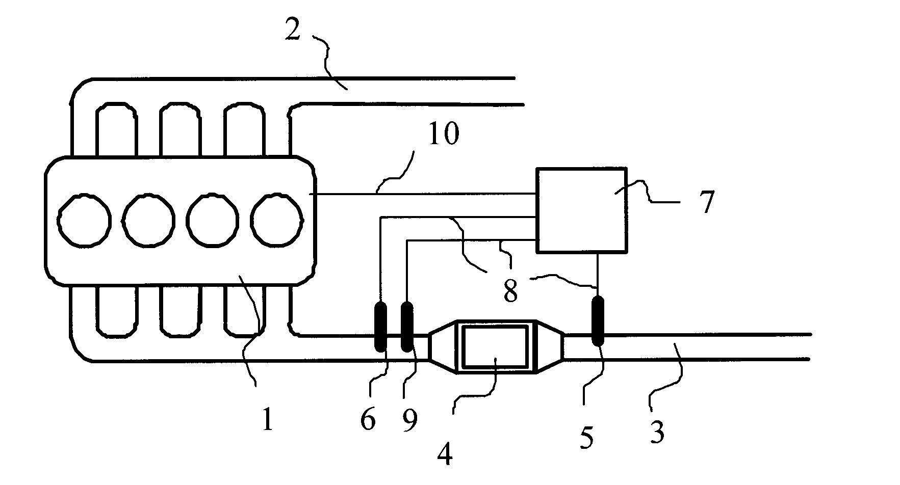
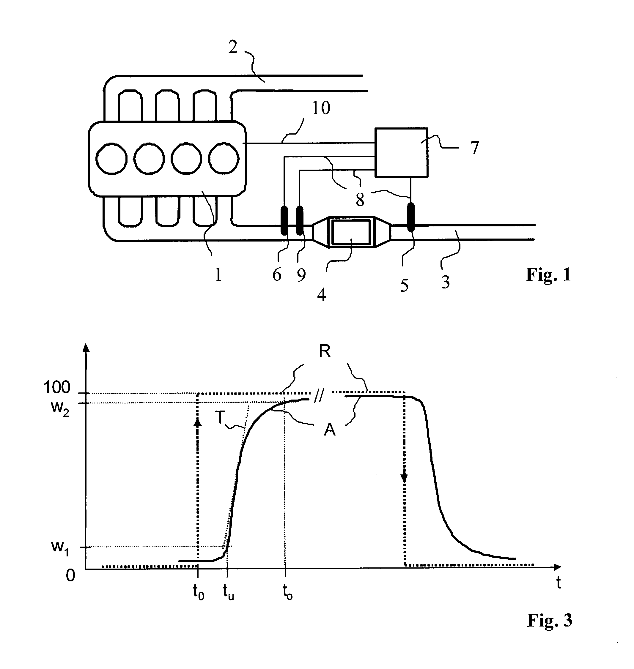
[0023]The embodiment of the system illustrated schematically below in FIG. 1 is to be understood as an advantageous embodiment considered to be merely exemplary and in no way limiting and shows an internal combustion engine 1 preferably formed as a spark ignition engine for driving a motor vehicle (not illustrated), which obtains its combustion air via an intake air line 2 and obtains fuel via a fuel supply. The fuel is preferably directly injected via injection valves in such a way that an air / fuel mixture to be burned is formed in the combustion chambers of the engine 1, which is not illustrated in greater detail.

[0024]Combustion exhaust gases produced during combustion of the air / fuel mixture are fed via an exhaust gas system 3 to an exhaust gas catalytic convertor 4 for catalytic exhaust gas purification. The exhaust gas catalytic convertor 4 can be a three-way catalytic convertor with oxygen storage capability that is part of an exhaust gas purification system that may contain ...


PUM


Abstract

A method for diagnosing an exhaust gas catalytic convertor and/or an exhaust gas sensor arranged downstream and/or upstream of the exhaust gas catalytic convertor in an exhaust gas system of a motor vehicle internal combustion engine. The internal combustion engine is operated with an air/fuel mixture having a substoichiometric air/fuel ratio. The internal combustion engine is switched off and an unfired towed operation with disabled fuel supply is performed in which air drawn in by the internal combustion engine is conveyed through the exhaust gas system to the exhaust gas catalytic convertor and exhaust gas sensor. The internal combustion engine is then operated with a substoichiometric air/fuel ratio and a signal of the exhaust gas sensor is evaluated with regard to a predefinable evaluation criterion, the signal being provided at least in a period of time between switch-off and the subsequent self-running of the internal combustion engine.

Description

BACKGROUND AND SUMMARY OF THE INVENTION[0001]Exemplary embodiments of the present invention relate to a method for diagnosing an exhaust gas catalytic convertor and / or an exhaust gas sensor arranged downstream and / or upstream of the exhaust gas catalytic convertor in an exhaust gas system of a motor vehicle internal combustion engine, with which a signal of the exhaust gas sensor is evaluated with regard to a predefinable evaluation criterion.[0002]A large number of methods have already been proposed for diagnosis of three-way catalytic convertors with oxygen storage capability, with which the effect of a sudden change in the air / fuel ratio during operation of a motor vehicle internal combustion engine is evaluated with regard to various signal parameters of an exhaust gas probe arranged in particular behind the catalytic convertor.[0003]For example, German Patent Document DE 10 2006 010 769 A1 discloses making a sudden change from engine operation with a leaner air / fuel ratio to en...

Claims


Application Information

Patent Timeline
IPC IPC(8): F01N11/00
CPCF01N11/00F01N11/007F01N2550/02F01N2550/03F02D41/042F02D41/123F02D41/1495F02D41/22F02D41/222Y02T10/40F01N2590/11
Inventor IMEROSKI, BAJRAM
Owner DAIMLER AG
Why Eureka
Try Eureka