Lightguide phototherapy apparatus

a lightguide and phototherapy technology, applied in the field of lightguide phototherapy apparatus, can solve the problems of cumbersome wearer, reduced light intensity per unit area, and difficulty in adjusting the lightguide, so as to reduce the heat dissipation per unit area, reduce the effect of light intensity generated per unit area

Inactive Publication Date: 2013-11-14
POLYPHOTONIX
View PDF3 Cites 16 Cited by
  • Summary
  • Abstract
  • Description
  • Claims
  • Application Information

AI Technical Summary

Benefits of technology

[0058]The present invention is based on the discovery that heat dissipation in light sources for eye masks can be effectively solved by using area light sources and by extending their size so that they are significantly larger than the eye. The light intensity generated per unit area can therefore be reduced and thus the associated heat dissipation per unit area is also reduced. To compensate for the reduced luminance, the total light output is effectively coupled into a lightguide, collected and emitted into the eye or onto the eyelids.

Problems solved by technology

For example, diabetic retinopathy is a condition caused by diabetes in which damage to the retina occurs, which can lead to impairment of vision or blindness.
LEDs are substantially rigid and most configurations cause some degree of discomfort to the user, especially if the device is to be used while sleeping.
In particular LED sources generate heat, causing discomfort.
Such a solution requires a separate light source, which is cumbersome for the wearer.
The device uses a lightbulb, making it cumbersome and bulky.
The disclosure does not address the type of light source to be used in such devices.
The proposed device is essentially a pair of glasses which are bulky in construction.
It is clear that LED and incandescent based devices have disadvantages in terms of either having rigid components or dissipation of heat generated by spot sources.
The disclosure does not offer power efficient solutions.
The electroluminescent strip operates at high voltages and its power efficiency is not ideal.
The disclosure does not offer means to reduce the heat emitted per area.

Method used


Image

  • Lightguide phototherapy apparatus
  • Lightguide phototherapy apparatus
  • Lightguide phototherapy apparatus

Examples


example 1

Retinopathy Device

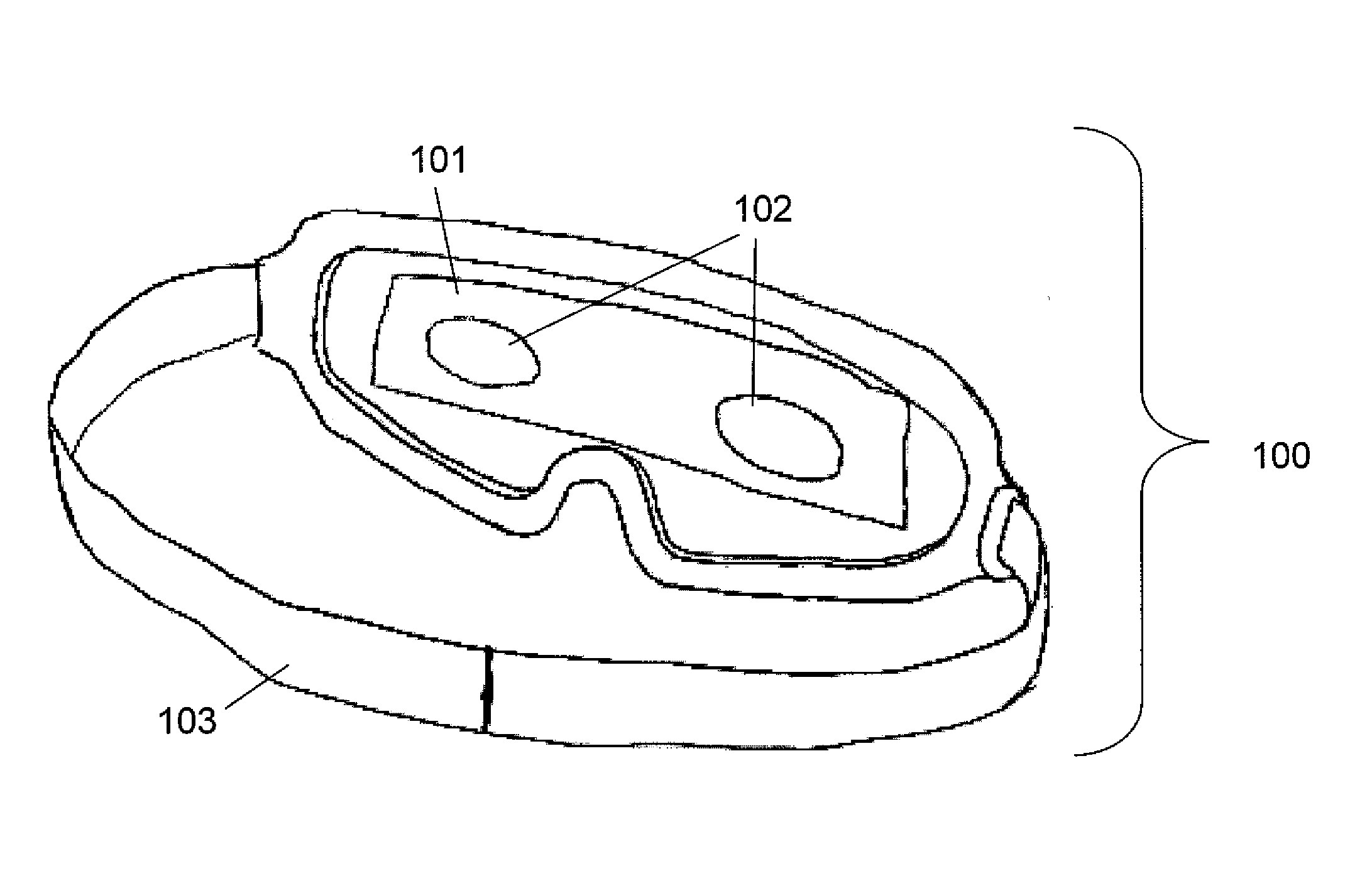
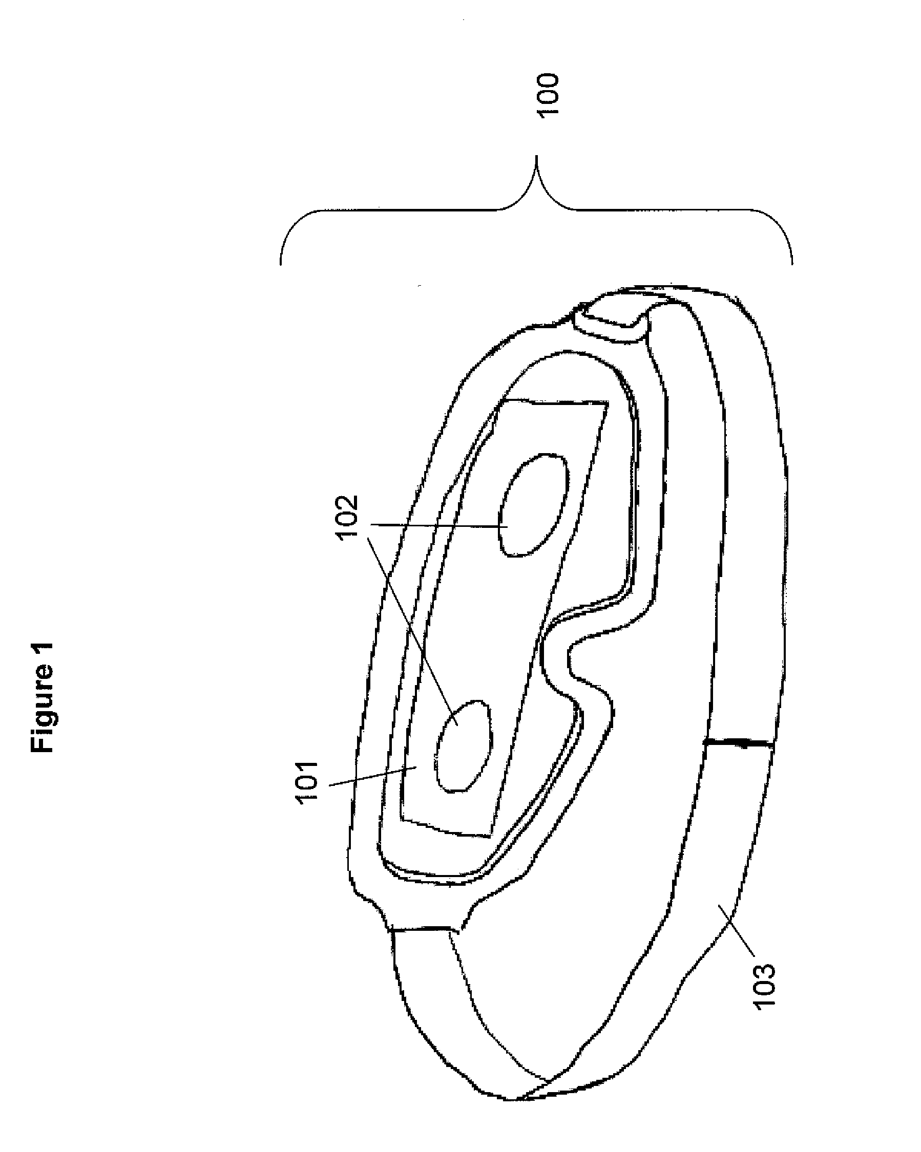
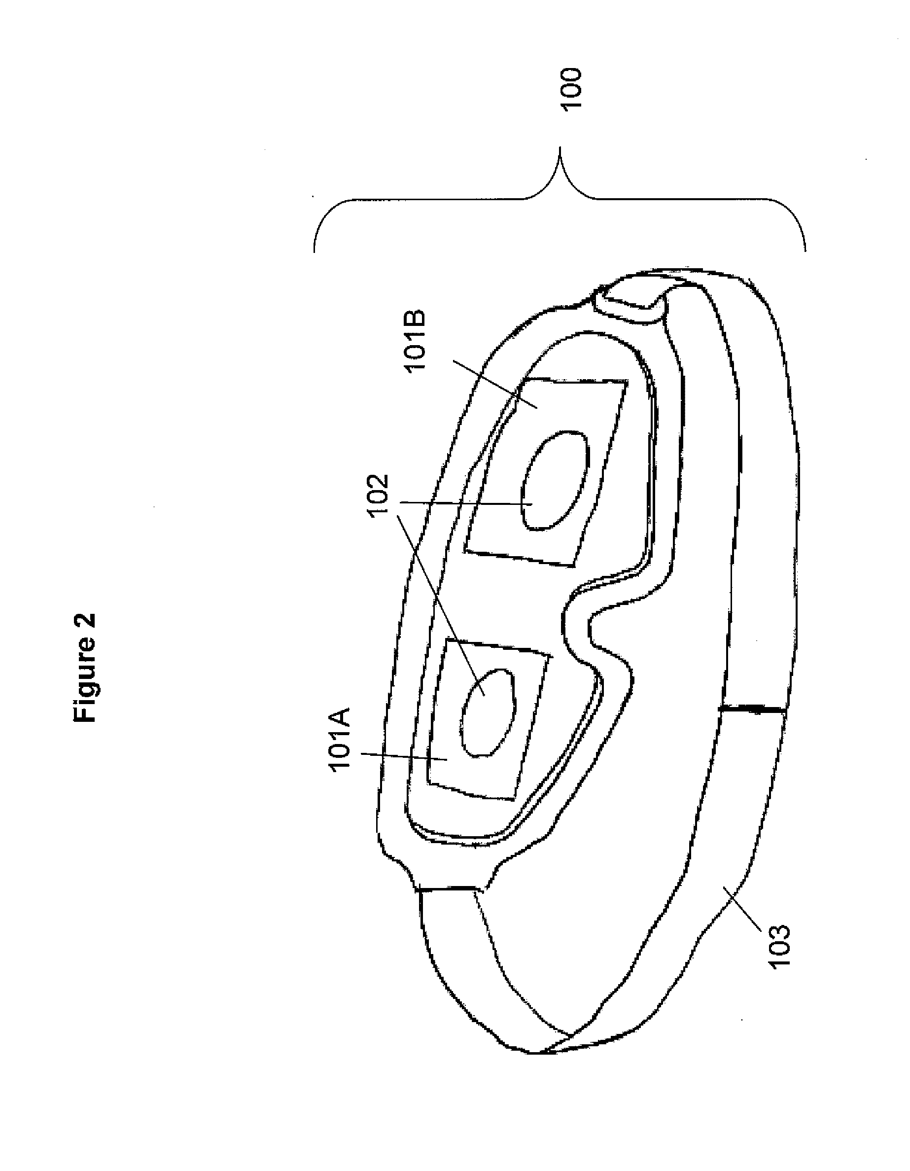
[0096]In patent application GB2410903A, Arden describes an eye mask device using inorganic LED light sources to illuminate the eyes of patients suffering from retinal diseases during their sleep. Because the treatment is carried out during sleep a phototherapy device with minimum discomfort for the user is advantageous. Because of the low light intensity required and the long illumination time available a passive phototherapy device using luminophore for slow release of light is particularly suitable. This example describes such device.

[0097]A light guide sheet element (less than 2 mm thick in thickness) could be moulded in the shape of an eye mask as to cover the eye of a patient as shown in FIG. 1. The element is formed by injection moulding silicone resin containing 0.1% of Lumogen F Green 850 (BASF). The light guide is coated on both sides with a 5 microns thick lower index polymer such as polychlorotrifluoro-ethylene.

[0098]A blue light emitting OLED is formed ...


PUM


Abstract

An apparatus (20) for directing electromagnetic radiation into a respective pupil of at least one eye of a user is disclosed. The apparatus comprises first radiation emitting means comprising at least one radiation emitting layer (8) adapted to emit electromagnetic radiation and second radiation emitting means (6} adapted to direct electromagnetic radiation into at least one eye and/or onto at least one eyelid of a user. A light guide (1) is adapted to receive radiation emitted by the first radiation emitting means and to direct at least part of the radiation to the second radiation emitting means, wherein a total surface area of the first emitting radiation means from which radiation is emitted is larger than a total cross sectional area of a beam of radiation entering the or each pupil of the user in use, in a direction transverse to an optical axis of the beam.

Description

[0001]The present invention relates to apparatus for radiation treatment devices of the eye. The invention relates particularly, but not exclusively, to radiation treatment apparatus for treating diabetic retinopathy.BACKGROUND OF THE INVENTION[0002]Light treatment of the eye can be used for a variety of therapeutic purposes, including retinopathy, modifying biological rhythms, psychiatric disorders and depression. For example, diabetic retinopathy is a condition caused by diabetes in which damage to the retina occurs, which can lead to impairment of vision or blindness. The condition can be treated by preventing the complete dark adaptation of the eye by illuminating the eyes / eyelids during sleep. The required wavelength for this treatment corresponds to the scotopic sensitivity of the eye, approximately 480 to 510 nm. Ideally a comfortable mask would be required for light treatments on the eye, especially if the therapy is conducted during sleep.[0003]Several examples of light the...

Claims


Application Information

Patent Timeline
Patent Type & Authority Applications(United States)
IPC IPC(8): A61N5/06
CPCA61N5/0613A61N2005/0648A61N2005/0653A61N2005/0656A61F2009/00863A61N2005/063A61N2005/0665
Inventor VERES, JANOSMIREMONT, CHRISTOPHE OLIVIERHILL, DUNCAN JOHN
Owner POLYPHOTONIX
Why Eureka
Try Eureka