Integrated Circuit Architecture with Strongly Coupled LC Tanks

a technology of integrated circuits and lc tanks, applied in the direction of pulse automatic control, resonance circuit tuning, oscillation generators, etc., can solve the problems of power consumption compromise, phase noise compromise, and difficult design of such vcos

Active Publication Date: 2013-11-21
NANYANG TECH UNIV
View PDF4 Cites 18 Cited by
  • Summary
  • Abstract
  • Description
  • Claims
  • Application Information

AI Technical Summary

Benefits of technology

[0007]According to the Detailed Description, an integrated circuit architecture for a radio frequency (RF) circuit is provided. The integrated circuit architecture includes a primary and one or more secondary LC tank circuits. The one or more secondary LC tank circuits are strongly coupled to the primary LC tank circuit and to each other either magnetically, electrically or a combination of magnetic and electric coupling.
[0008]In addition, a voltage controlled oscillator for a radio frequency (RF) circuit is provided. The voltage controlled oscillator includes a primary and one or more secondary coupled LC tank circuits. Each LC tank circuit of the primary and one or more secondary LC tank circuits includes an inductor and a capacitive device connected in parallel. Between or among the primary and one or more secondary coupled LC tank circuits, there exists strong electric or magnetic coupling or a combination of electric and magnetic coupling.
[0009]Further, an injection locked frequency divider having a predetermined frequency division ratio is provided. The injection locked frequency divider includes a primary and one or more secondary LC tank circuits. Each LC tank circuit of the primary and the one or more secondary coupled LC tank circuits includes an inductor and a capacitive device connected in parallel. Each LC tank circuit of the primary and the one or more secondary coupled LC tank circuits is strongly coupled to each other for band pass filtering an input frequency to generate an output frequency filtered in accordance with the predetermined frequency division ratio.

Problems solved by technology

It is often very challenging to combine all the best performances without much tradeoff which makes the design of such VCO very difficult.
Generally, however, the phase noise is compromised with the tuning range which in turn is compromised with power consumption.
However, such typical ILFDs have a relative narrow operation frequency range.

Method used


Image

  • Integrated Circuit Architecture with Strongly Coupled LC Tanks
  • Integrated Circuit Architecture with Strongly Coupled LC Tanks
  • Integrated Circuit Architecture with Strongly Coupled LC Tanks

Examples


Embodiment Construction

[0030]The following detailed description is merely exemplary in nature and is not intended to limit the invention or the application and uses of the invention. Furthermore, there is no intention to be bound by any theory presented in the preceding background of the invention or the following detailed description of the invention.

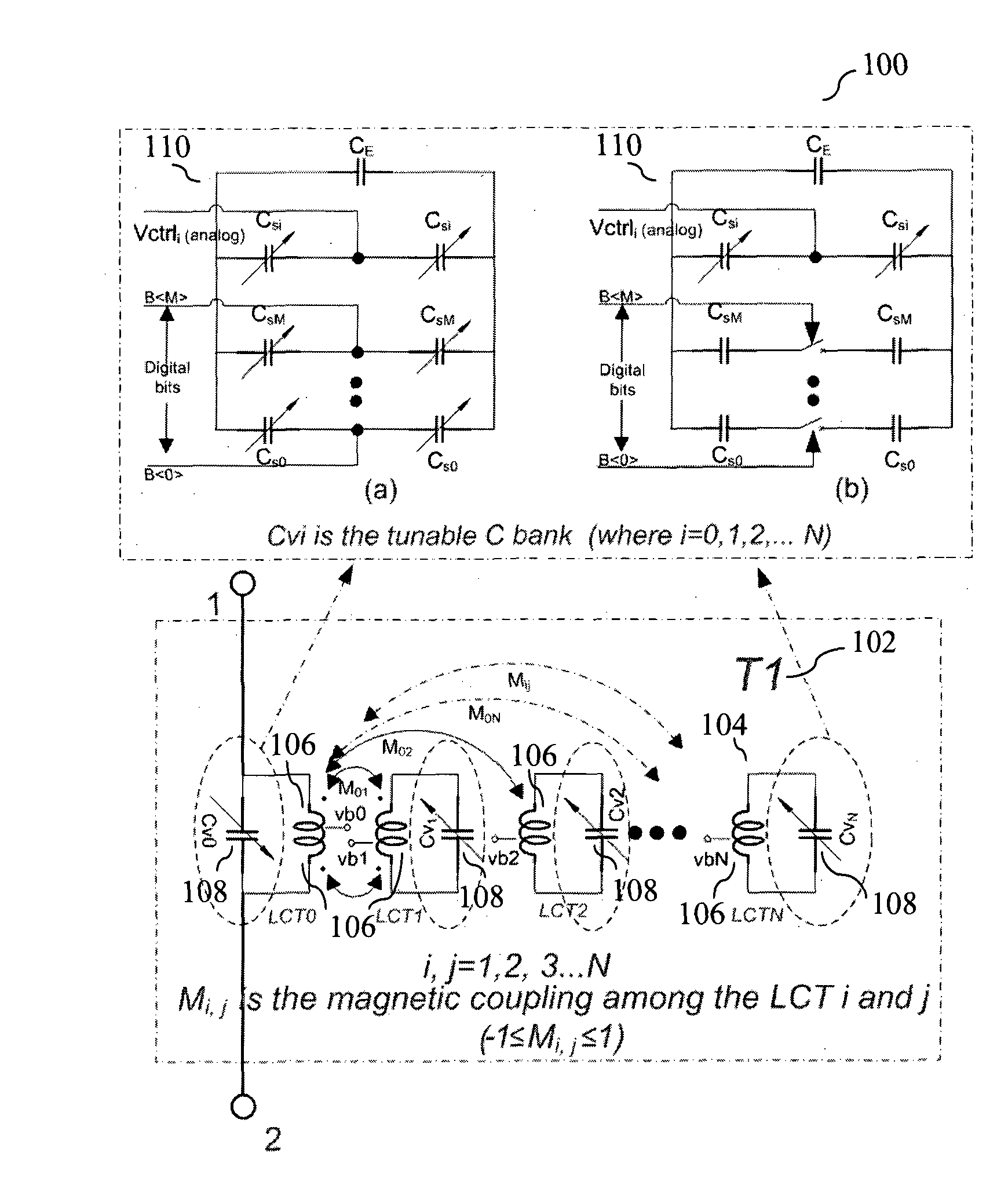
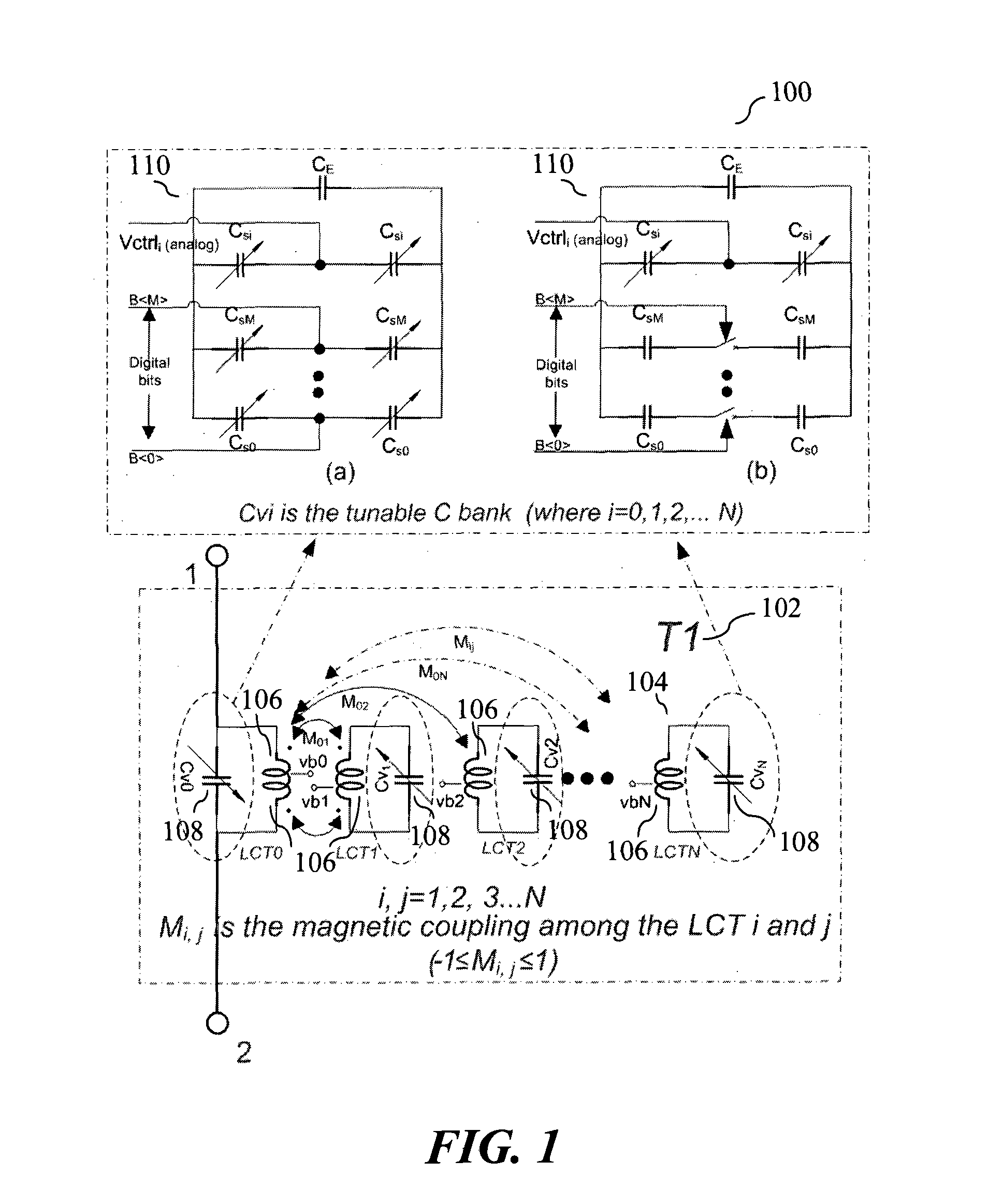
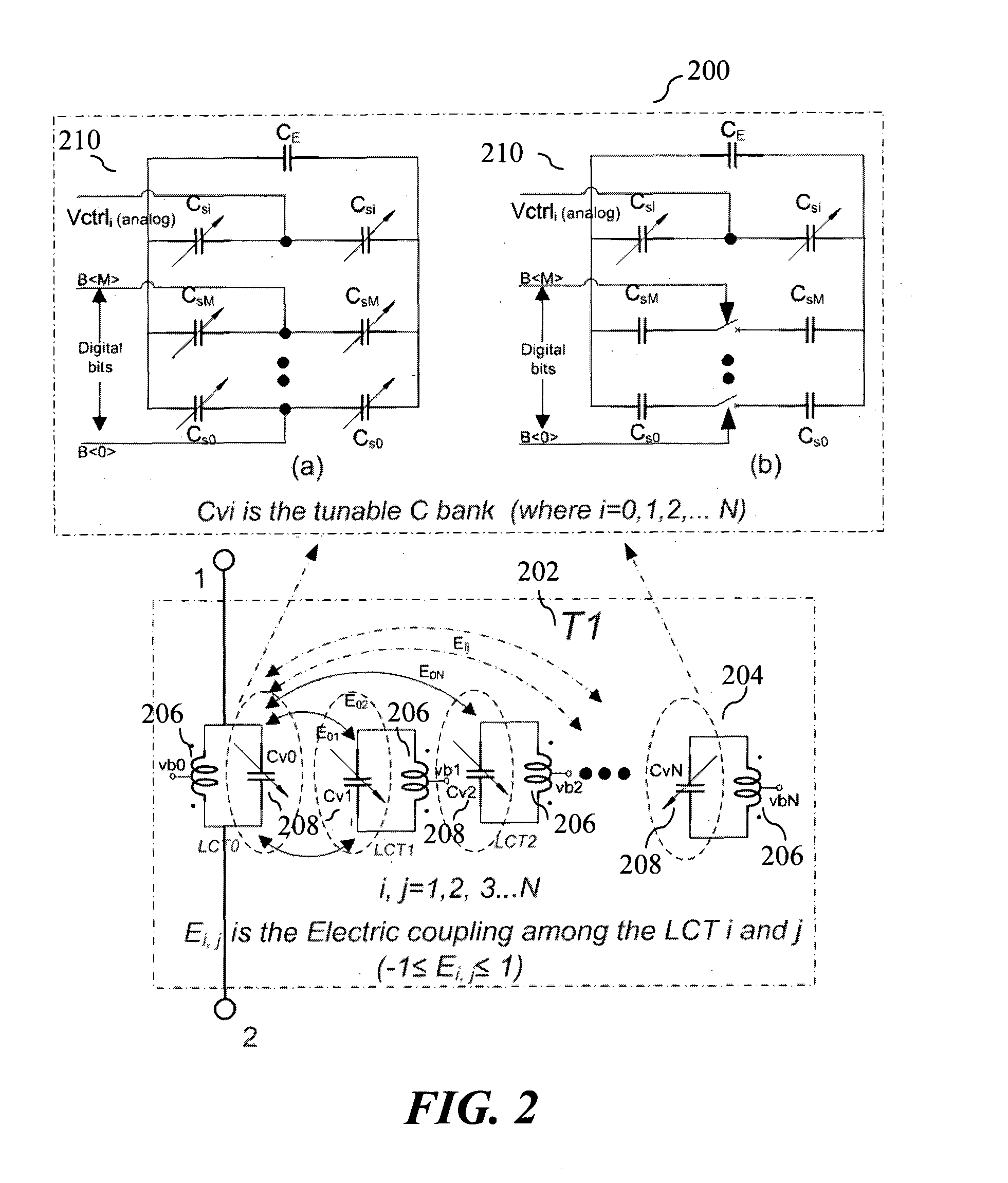
[0031]The present embodiment relates to a design of a radio frequency (RF) / Microwave / Millimeter-wave wideband voltage controlled oscillator (VCO) such as those intended for use in wireless communication applications for IEEE 802 (e.g., WiFi, WiMax, LTE, and IEEE 802.11ad) and applications for other commercial and military communications where high performance is required. High performance VCOs generally include a tank circuit which is formed by the parallel combination of inductance and capacitance. The present embodiment is a design of a VCO which can achieve quality performance with optimum tradeoff and is suitable for today's wireless applications. Many V...


PUM


Abstract

An integrated circuit for a radio frequency (RF) circuit such as a voltage controlled oscillator or an injection locked frequency divider is provided. The integrated circuit architecture includes a primary LC tank circuit comprising a first inductor and a first capacitive device connected in parallel and one or more secondary LC tank circuits, each comprising an inductor and a capacitive device connected in parallel. Each of the one or more secondary LC tank circuits is strongly coupled to the primary LC tank circuit and to each other either electrically, magnetically or a combination of electrically and magnetically.

Description

CROSS-REFERENCE TO RELATED APPLICATION[0001]The present application claims priority to U.S. Provisional Patent Application No. 61 / 405,244, filed Oct. 21, 2010.FIELD OF THE INVENTION[0002]The present invention generally relates to integrated circuit architecture including multiple LC tanks, and more particularly relates to circuits such as voltage controlled oscillators or injection locked frequency dividers which include multiple LC tanks.BACKGROUND OF THE DISCLOSURE[0003]Typically, a radio frequency (RF) communication device includes an RF front end which, more recently, has been enabled in a RF integrated circuit. The RF front end, conventionally, has a signal source, in most cases a voltage controlled oscillator (VCO), which is ubiquitous with modem transceivers and forms an integral part of frequency synthesizers or Phase Locked Loops (PLLs). The performance of the VCO may have an effect in the overall performance of the system if not properly designed. For example, very low pha...

Claims


Application Information

Patent Timeline
Patent Type & Authority Applications(United States)
IPC IPC(8): H03H7/01H03L7/00
CPCH03B2200/0074H03J3/20H03J2200/10H03H7/0115H03L7/00H03B5/1265H03B5/1218H03B5/1296H03B5/1215H03B5/1243H03B5/1228H03B19/00
Inventor MA, KAI XUEMAHALINGAM, NAGARAJANMOU, SHOUXIANYEO, KIAT SENG
Owner NANYANG TECH UNIV
Why Eureka
Try Eureka