
Anti-fog coating

a technology of anti-fog coating and anti-misting, which is applied in the direction of instruments, optical elements, transportation and packaging, etc., can solve the problems of shortening the anti-misting effect or anti-fog effect, affecting the general propagation of light, and affecting the stability of optical components, etc., to achieve the effect of enhancing stability with respect to hydrolysis

Active Publication Date: 2013-11-21
CARL ZEISS VISION INT GMBH
View PDF2 Cites 14 Cited by
  • Summary
  • Abstract
  • Description
  • Claims
  • Application Information

AI Technical Summary

Benefits of technology

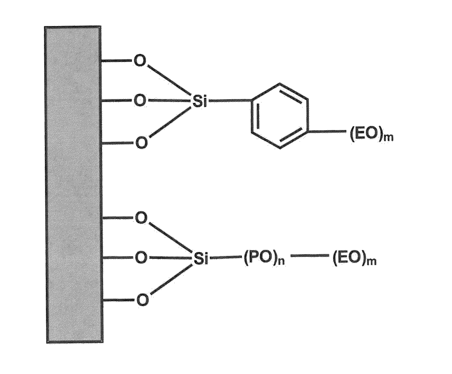
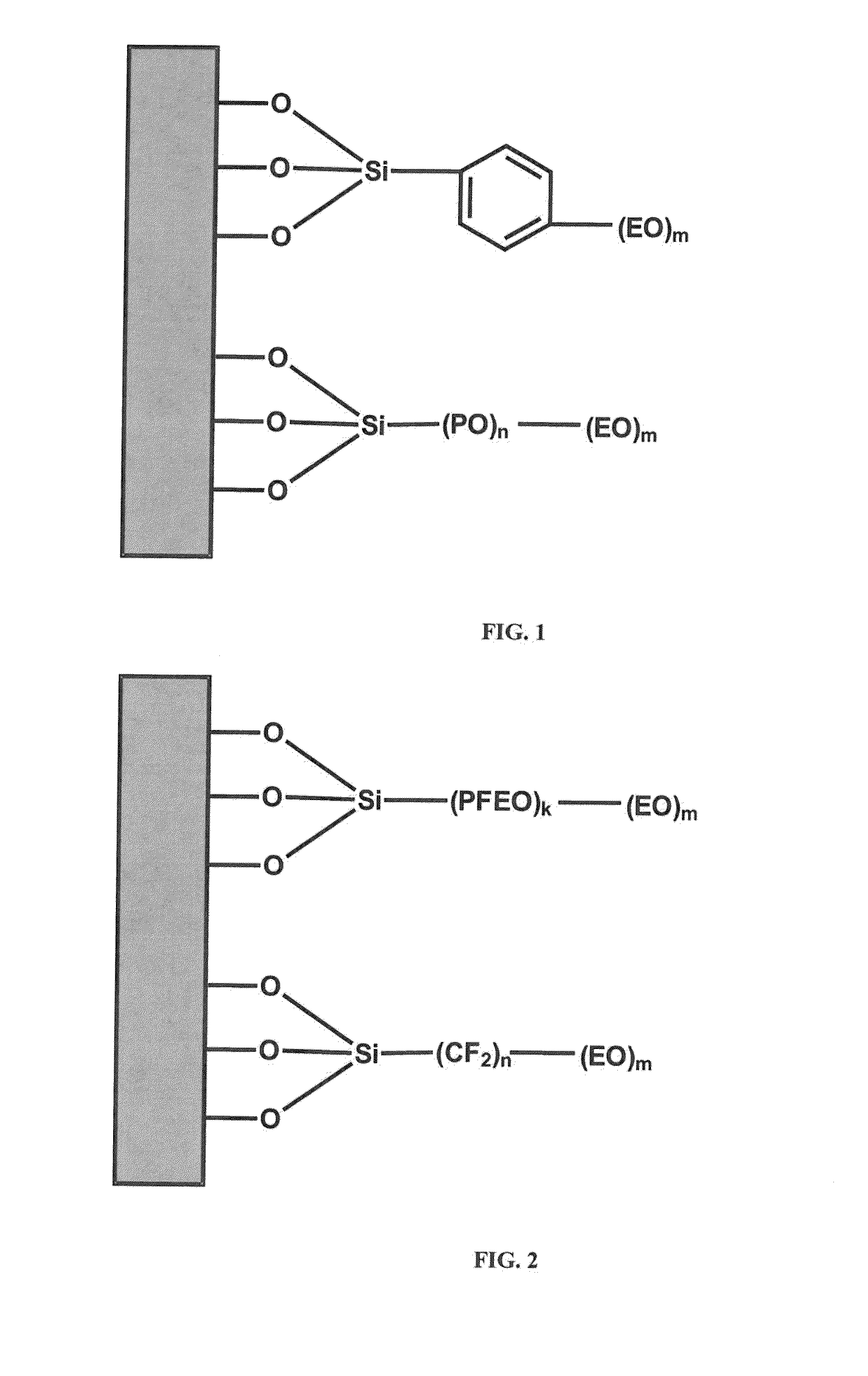
The present invention provides an anti-fog coating for optical components that has improved stability with respect to hydrolysis. This is achieved by using a compound with a specific hydrophobic group that shields the molecules of the anti-fog coating from water and a terminal hydrophilic group that prevents unwanted adsorption on the surface of the optical component. The compound can also be crosslinked to enhance the stability of the anti-fog coating.

Problems solved by technology

The problem of misting affects optical components in general.
The reason why a misted lens appears milky is that the droplets disrupt the propagation of light.
A phenomenon common to these products is that the anti-mist effect or anti-fog effect is not long-lasting, and it is instead necessary to apply the solution regularly to the surface.

Method used


Image

  • Anti-fog coating
  • Anti-fog coating
  • Anti-fog coating

Examples


example 1

[0063]A polyethylene glycol (PEG) modified trichlorosilane (Mn˜500 g / mol) is dissolved in toluene so that a 5 mass% solution is obtained. A glass having an antireflective coating but no CleanCoat® is dipped into the solution and then air-dried. Any remaining over-coating is removed by rubbing with a dry cloth.

example 2

[0064]A polyethylene glycol (PEG) modified trichlorosilane (Mn˜500 g / mol) is dissolved in toluene so that a 2.5 mass% solution is obtained. A glass having an antireflective coating but no CleanCoat® is dipped into the solution and then air-dried. Any remaining over-coating is removed by rubbing with a dry cloth.

[0065]By covalently attaching the PEG-modified silane to the substrate surface, coatings are obtained in Examples 1 and 2 which provide anti-fogging properties. Due to the higher concentration of the PEG-modified silane, the anti-fogging effect provided in Example 1 is higher than in Example 2.

example 3

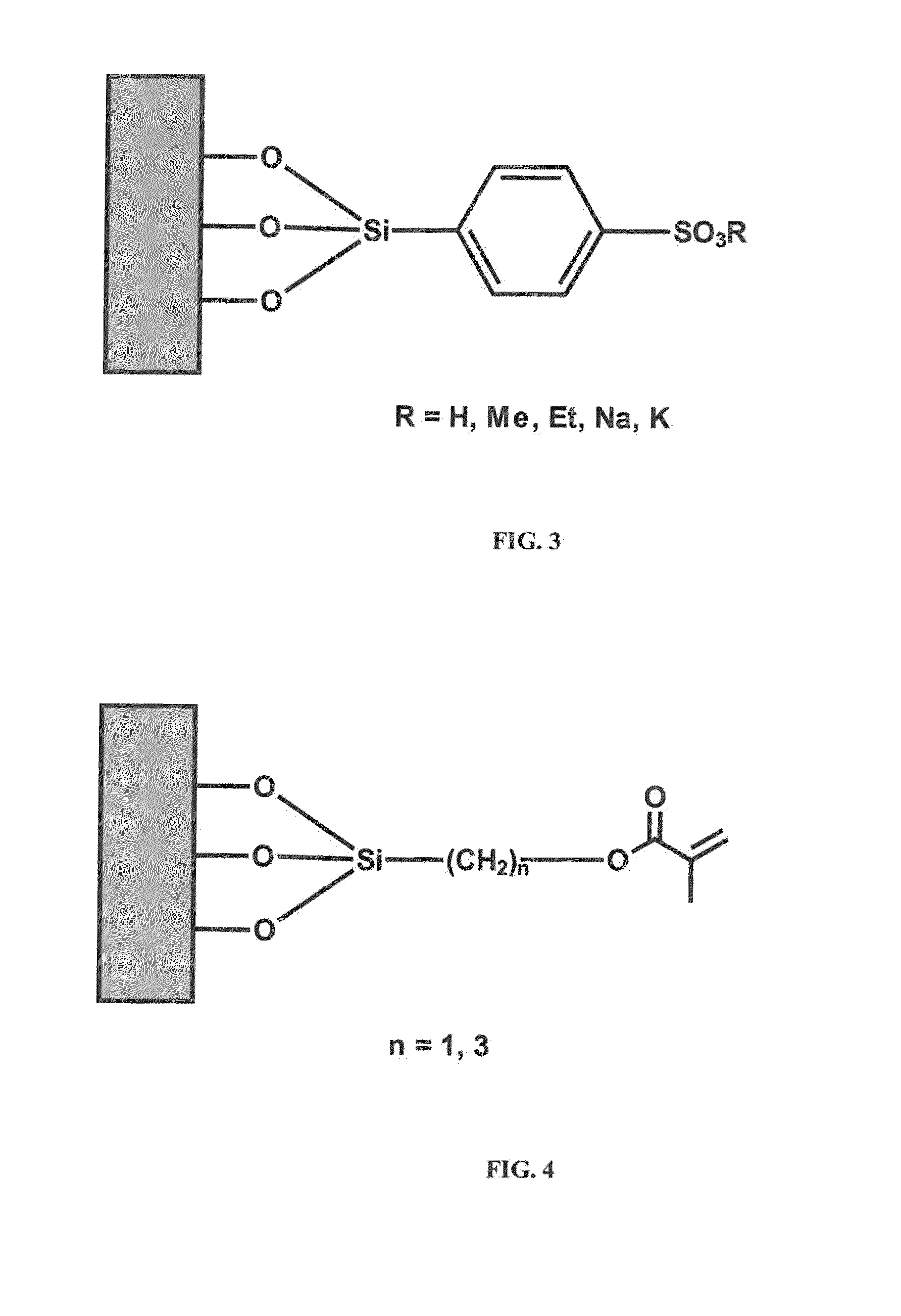
[0066]9.98 g 3-methacryloxypropyl trichlorosilane are dissolved in 490 ml toluene. A glass is stored in said solution for one hour and then air-dried. In a second step, the glass is dipped into a solution made of 5.0 g 2-hydroxyethyl methaerylate (HEMA), 1.0 g trimethylol propanetriacrylate (TMPTA) and 0.5 g diphenyl-(2,4,6-trimethylbenzoyl) phosphine oxide in 50 ml toluene, followed by curing with a Panacol UV-D-1000 lamp.


PUM

PropertyMeasurementUnit
Thicknessaaaaaaaaaa
Hydrophilicityaaaaaaaaaa

Abstract

An optical component having an anti-fog coating obtainable by covalent attachment of a silane RoXmSiAn to the surface of the optical component, whereinm=1-3, n=1-2 and o=0-1, with the proviso that m+n+o=4;X is halogen or C1-4-alkoxy, and for m=2 or 3 the individual radicals X may be identical or different,R is C1-4-alkyl,A has the structure -A1-A2, in which -A1-is a hydrophobic group bonded to Si, and -A2 represents a terminal hydrophilic group bonded to A1, -A1-is selected from -arylene-; —C1-6-alkylene-arylene-; -arylene—C1-6-alkylene-; —C1-6-alkylene-arylene—C1-6-alkylene-; -poly(C3-6-alkoxylene)-, fluorinated or perfluormated -alkylene-, fluorinated or perfluormated -poly(C2-6-alkoxylene)-, or a combination thereof,and -A2 is poly(meth)acrylate,and for n=2 the individual radicals A may be identical or different,and where -A2 comprises monomer units selected from CH2═C(CH3)COOC1-4-alkyl, CH2═C(H)COOC1-4-alkyl hydroxyethylene methacrylate, 2-acrylamido-2-methylpropanesulphonic acid, trimethylolpropane triacrylate and pentaerythritol tetraacrylate or mixtures thereof.

Description

CROSS REFERENCE TO RELATED APPLICATION[0001]This application claims priority of German patent application no. 10 2012 009 691.7, filed May 15, 2012, the entire content of which is incorporated herein by reference.FIELD OF THE INVENTION[0002]The present invention relates to an anti-fog coating on an optical component and also to a method for its production.BACKGROUND OF THE INVENTION[0003]Present-day eyewear lenses (corrective spectacles, sunglasses, ski / sports eyewear, protective goggles) mist up under adverse conditions. These conditions are, on the one hand, the transition from a cold environment into a warm environment (for example, entering the home from outside in cold temperatures in the winter, or leaving an air-conditioned building in a country with tropical climate conditions), and on the other hand if the eyewear lens makes contact with a source of warm / hot air with high relative humidity. Once the eyewear has misted up, the wearer must typically take off his or her eyewea...

Claims


Application Information

Patent Timeline
IPC IPC(8): G02B27/00
CPCG02B27/0006G02B1/18C03C17/30C03C17/34C09D4/00C09D5/00C09D183/06C08G77/14C03C2217/75C03C2218/111C09K2323/033C09D133/14G02B1/11
Inventor GLOEGE, THOMASHUGENBERG, NORBERTVON BLANCKENHAGEN, BERNHARDKRAUS, STEFAN
Owner CARL ZEISS VISION INT GMBH
Learn More