
Thermally and electrically highly conductive aluminium strip

a technology of high thermal and electrical conductivity and aluminium strip, which is applied in the direction of insulation conductors/cables, conductors, lighting and heating apparatus, etc., can solve problems such as heat or electricity transfer problems, achieve and retain its consistently high heat and/or electricity conducting properties. , the effect of high thermal and/or electrical conductivity

Inactive Publication Date: 2013-11-21
HYDRO ALUMINIUM ROLLED PROD GMBH
View PDF3 Cites 5 Cited by
  • Summary
  • Abstract
  • Description
  • Claims
  • Application Information

AI Technical Summary

Benefits of technology

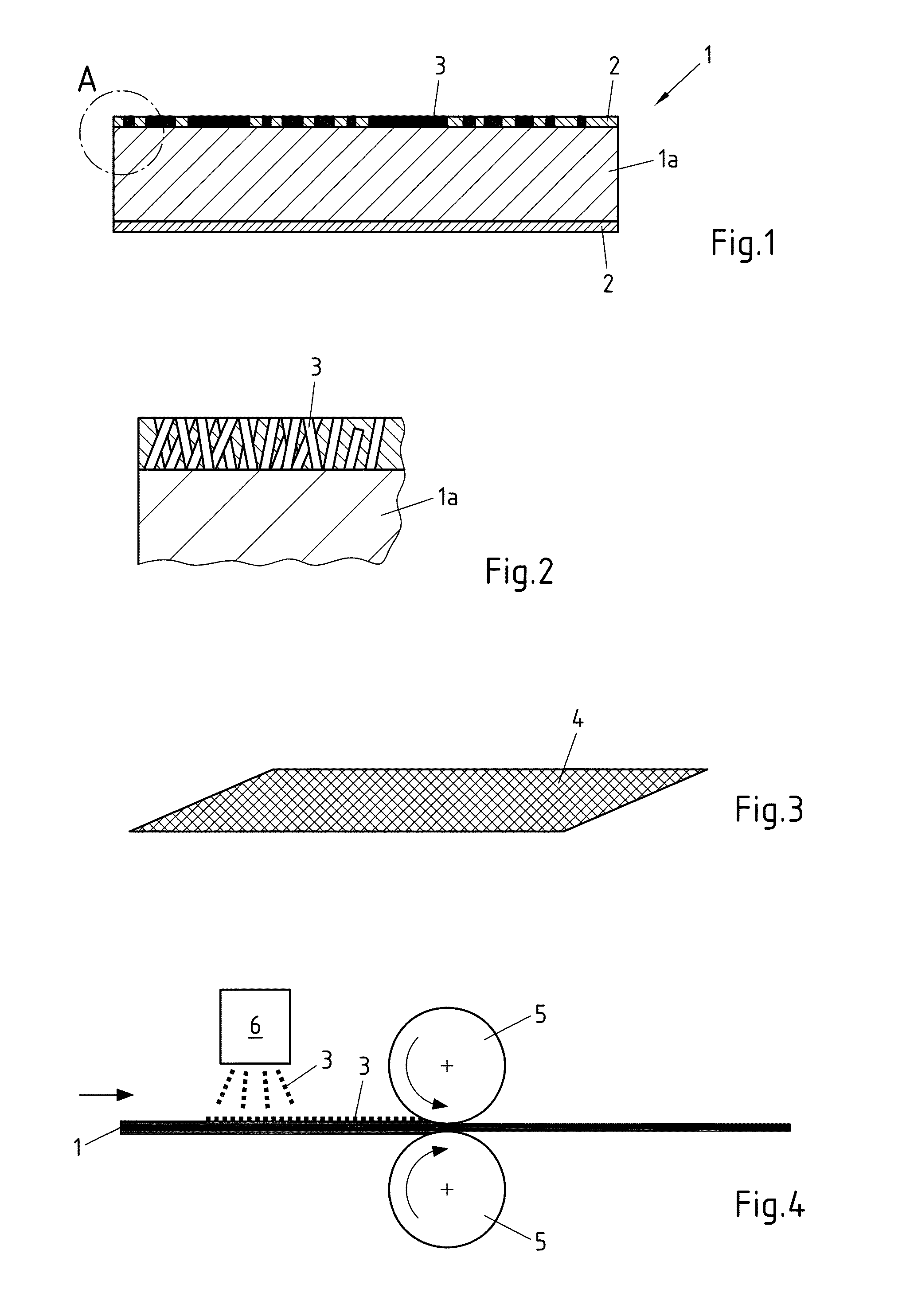
The patent describes a method for producing a strip or foil with high thermal and electrical conductivity by embedding nanoparticles into the surface of the strip or foil. The nanoparticles can be pressed into the surface easily using a mechanical force, and a bonding agent or primer can be used to prepare the surface for the nanoparticles. The nanoparticles can be distributed over the surface in a specific pattern or collected in texture recesses to improve adhesion. The method involves minimal investment costs and can be used with existing process steps. The functional particles can be deposited on the surface in the form of a dispersion, suspension, or powder, and rolling oil can be used to assist adhesion. The technical effects of the patent are improved thermal and electrical conductivity of the strip or foil, simplified production process, and improved adhesion of the nanoparticles to the surface.

Problems solved by technology

Battery electrodes and printed circuit boards certainly, but also current conducting cables and their plugs and contacts are often made from aluminium, because aluminium or aluminium alloys have particularly low electrical resistances.
On the other hand, the heat and electricity conducting properties of said aluminium oxide layer are significantly poorer, resulting in problems with the transfer of heat or electricity particularly at contact points between two different components.
However, this has not led to the desired result, because the aluminium oxide layer between the highly conductive coating and the core of the aluminium strip prevents said aluminium strip core from contributing to the conductivity thereof to its full extent.

Method used


Image

  • Thermally and electrically highly conductive aluminium strip
  • Thermally and electrically highly conductive aluminium strip

Examples


Embodiment Construction

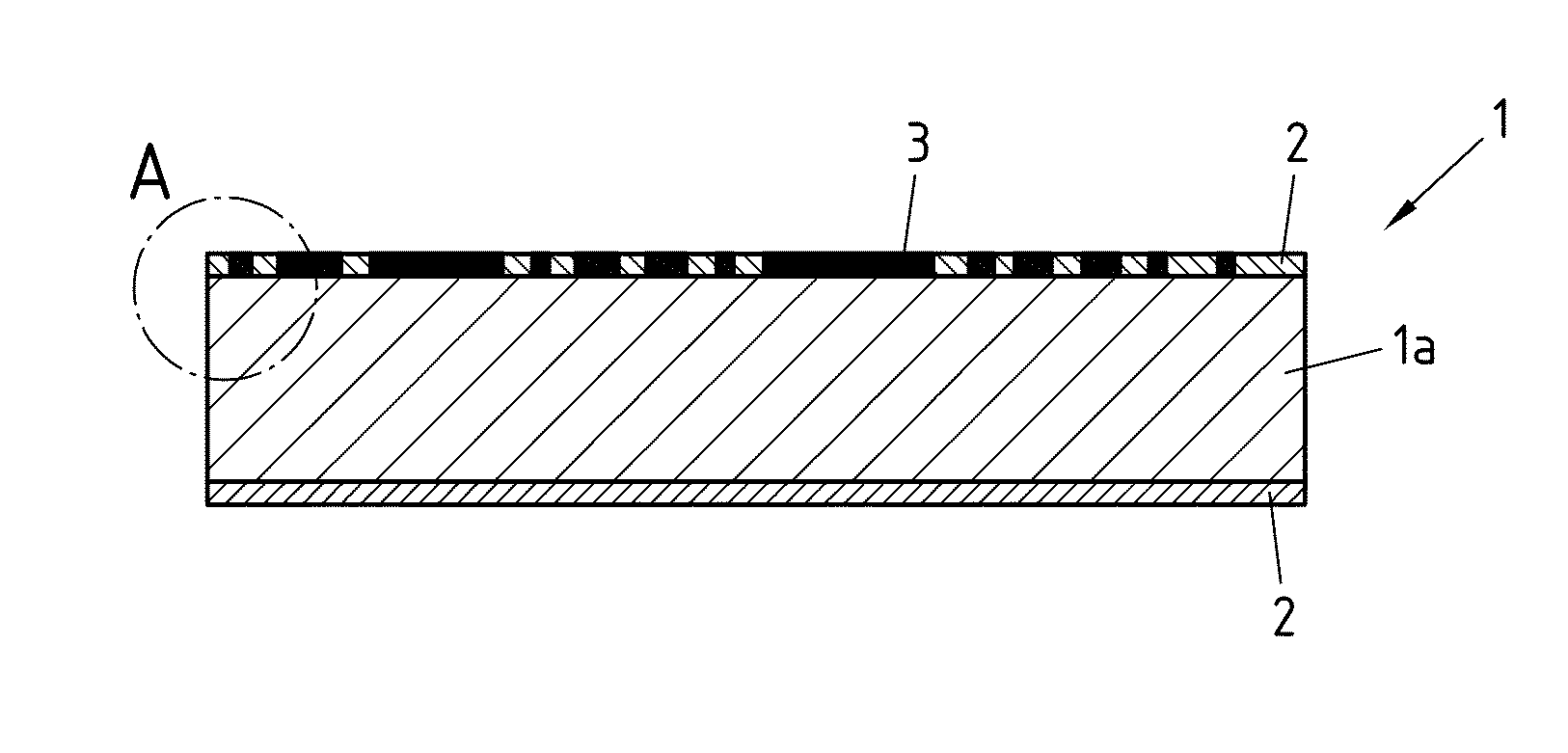
[0023]FIG. 1 is a schematic cross-sectional view of an embodiment of strip 1 having an oxide layer 2 on both sides thereof. Thermally and / or electrically highly conductive functional particles 3 are incorporated in upper oxide layer 2 and partially penetrate oxide layer 2. The embodiment of a strip 1 shown in FIG. 1 includes functional particles introduced on one side thereof. Of course, it is conceivable to provide highly conductive functional particles 3 in both oxide layers on strip 1. The highly conductive functional particles 3 are in contact with the core material 1a of strip 1, so that in the case of conducting current for example functional particles 3 convey the electric current into the core region of strip 1a without obstruction, the core region being highly conductive. Aluminium oxide layer 2 then no longer has a significant effect on the electrical and / or thermal conductivity of the strip 1 or foil according to the invention. Strip 1 according the invention may have a t...


PUM

PropertyMeasurementUnit
thickaaaaaaaaaa
thicknessaaaaaaaaaa
thicknessesaaaaaaaaaa

Abstract

The invention relates to a strip or foil (1) made from aluminium or an aluminium alloy that has an external oxide layer. The object of providing a strip or foil made from aluminium or an aluminium alloy in which the thermal and / or electrical conductivity remains consistently high regardless of the formation of an aluminium oxide layer is solved by arranging thermally and / or electrically highly conductive functional particles on one or both sides of the strip or foil, which functional particles at least partly penetrate the oxide layer of on the strip or foil.

Description

CROSS-REFERENCE TO RELATED PATENT APPLICATIONS[0001]This patent application is a continuation of PCT / EP2012 / 051232, filed Jan. 26, 2012, which claims priority to German Application No. 102011000395.9, filed Jan. 28, 2011, the entire teachings and disclosure of which are incorporated herein by reference thereto.FIELD OF THE INVENTION[0002]The invention relates to a strip or foil consisting of aluminium or an aluminium alloy that has an outer oxide layer. The invention further relates to a method for producing a strip or foil according to the invention and use thereof.BACKGROUND OF THE INVENTION[0003]Aluminium or aluminium alloys are used widely for electrically and / or thermally conductive components. Examples of such include solar absorbers, which are used in the field of solar thermal energy, that is to say the recovery of heat from the sun's rays. Battery electrodes and printed circuit boards certainly, but also current conducting cables and their plugs and contacts are often made ...

Claims


Application Information

Patent Timeline
Patent Type & Authority Applications(United States)
IPC IPC(8): F28F21/02H01B1/02H01B13/32
CPCF28F21/02H01B13/321H01B1/023C23C26/00C23C30/00
Inventor DENKMANN, VOLKERHAMPEL, ULRICHSIEMEN, ANDREASECKHARD, KATHRINSCHENKEL, WILHELMSEIFFERTH, OLIVER
Owner HYDRO ALUMINIUM ROLLED PROD GMBH
Learn More