
Liquid Fuel Combustion System

a combustion system and liquid fuel technology, applied in the direction of combustion types, domestic stoves or ranges, lighting and heating apparatus, etc., can solve the problems of high cost of lpg, and potential explosion hazards

Inactive Publication Date: 2013-11-28
GREEN HYDROTEC
View PDF15 Cites 16 Cited by
  • Summary
  • Abstract
  • Description
  • Claims
  • Application Information

AI Technical Summary

Benefits of technology

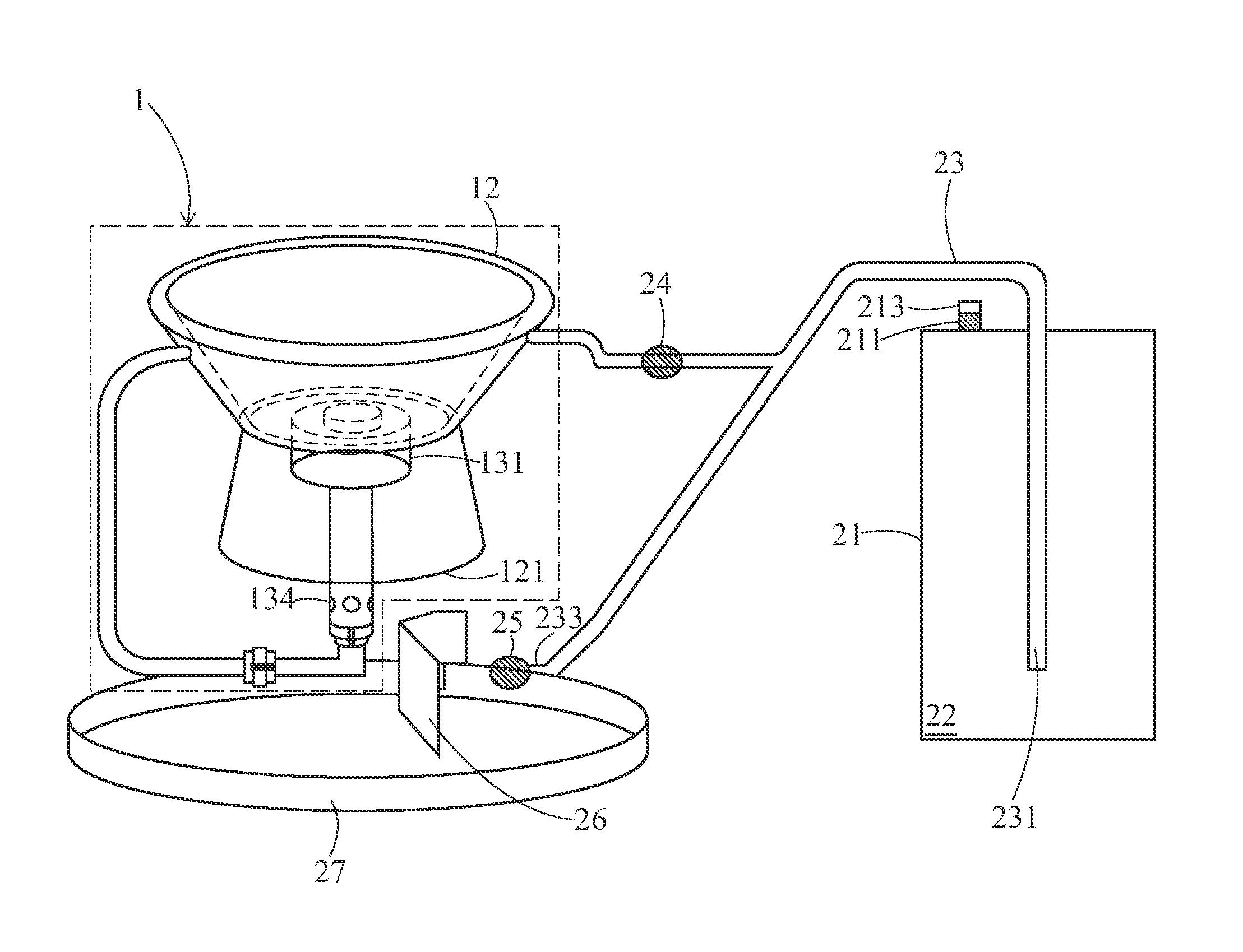
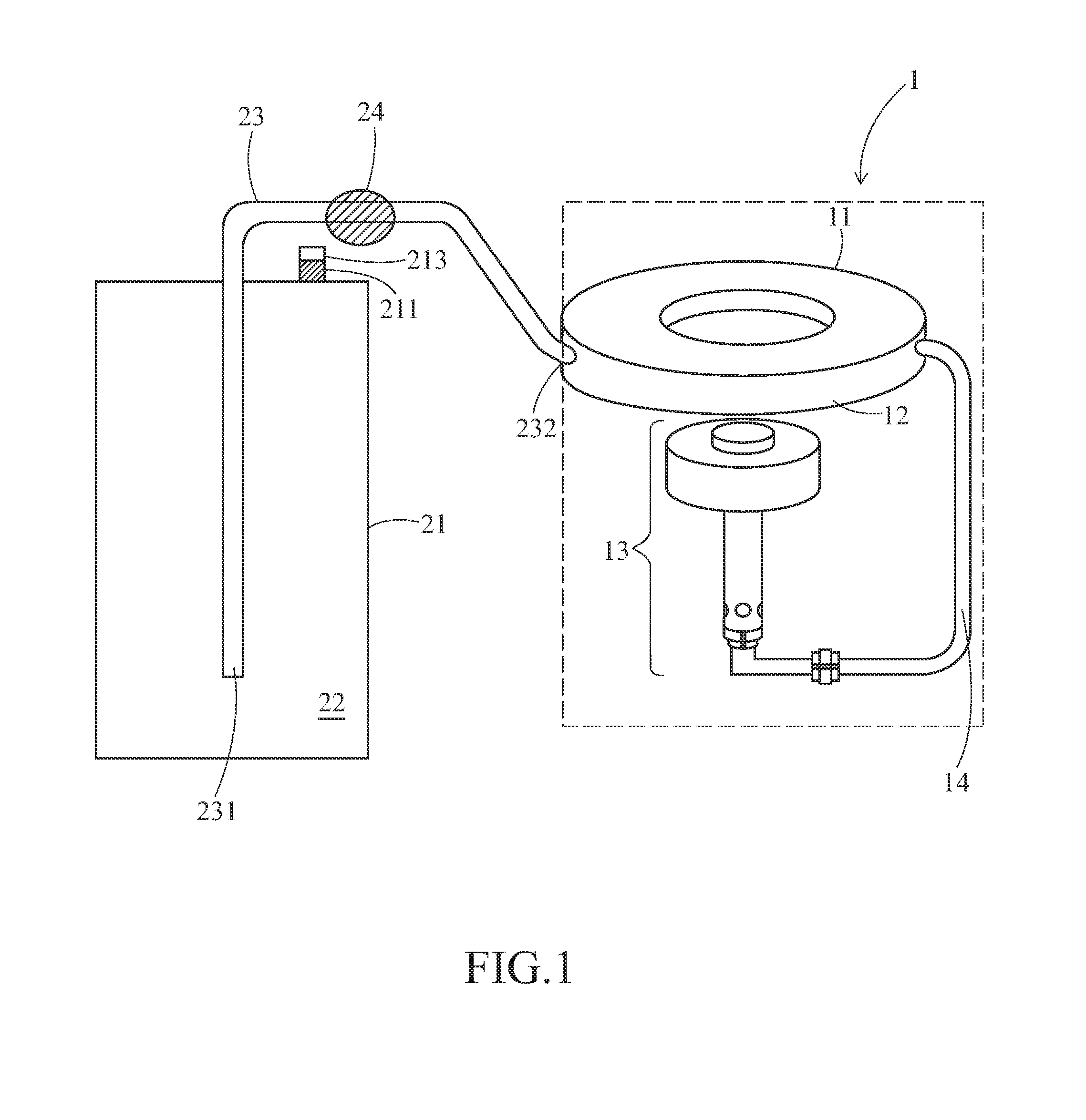
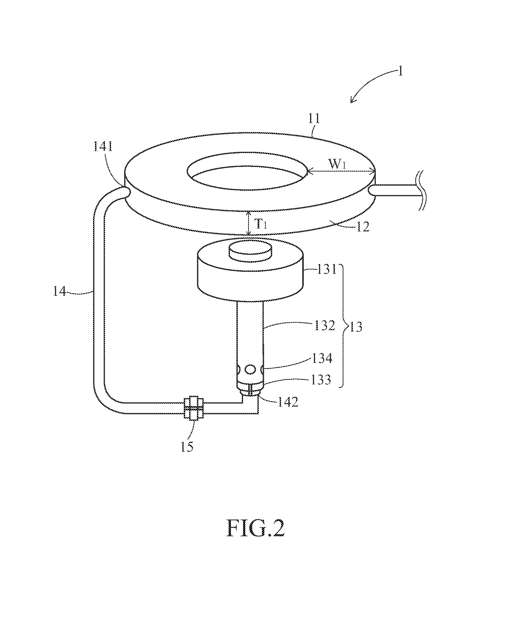
The invention is a liquid fuel combustion system that includes a vaporization unit, a burner assembly, and a liquid fuel tank. The system uses an ignition promoter to create a vapor pressure in the tank that drives the liquid fuel to be delivered out of the tank and vaporized in the vaporization space before being delivered to the burner assembly. The technical effect of this invention is a more efficient and controlled liquid fuel combustion system that can deliver consistent and reliable performance.

Problems solved by technology

However, in many remote area or developing countries, it is too costly to have a NG supply network facility.
But even LPG can be conveniently transported by storing LPG in a storage tank, it is not only expensive but also explosive when being leaked into air.
Because of LPG's high cost and potential explosion hazard, numerous attempts have been tried to develop a liquid fueled cooking stove such as a kerosene or methanol cooking stove.
However, none of them can be operated as convenience as a LPG stove because of the following reasons.
First, the liquid fuel cannot be conveniently delivered to the stove from its storage tank, and usually require an additional air pump or compressor or other driving force (e.g., hanging the storage tank at an elevation to provide enough gravitation force to force the fuel to flow to the stove).
But the use of the air compressor / pump will put the liquid fuel in an explosive danger because of low explosion limit.
The second reason giving rise to the fail of the liquid fueled cooking stove is that, the flash point of liquid fuel (e.g., kerosene or methanol) is too high to be easily ignited.
As a result, the liquid fuels cannot be ignited with an electronic igniter; they must be ignited using an “open flame” such as a flame torch or butane gun.
, the vaporization of kerosene is slow and difficult; this results in oily smell and smoke during burning. A
s to the methanol stove, the methanol flame during burning is unsteady and jumpy.

Method used


Image

  • Liquid Fuel Combustion System
  • Liquid Fuel Combustion System
  • Liquid Fuel Combustion System

Examples


examples

[0062]According to the ratio indicated in Tables 1 to 6, the liquid fuel (methanol or cleaning naphtha) or the mixture of the liquid fuel and stabilizer and / or heat transfer promoter were loaded into the storage space of liquid fuel storage tank to provide liquid fuel compositions, and a predetermined amount of ignition promoter was then added into the storage space. The liquid fuel storage tank was then shaken to uniformly mix the components of liquid fuel composition. The pressure of the liquid fuel storage tank was measured and recorded in the tables.

[0063]Thereafter, the flow rate of liquid fluid composition was controlled in the range of about 10 g / min to about 20 g / min. An electric igniter was disposed adjacent to the burning head to provide an arc to ignite the liquid fuel composition. The required time period to ignite the liquid fuel composition while obtain a steady flame strength (ignition time θ) was measured and recorded in the tables respectively. After obtaining the s...


PUM


Abstract

A liquid fuel combustion system is provided. The system comprises:a combustion stove, comprising a vaporization unit with a ring shape vaporization space, a burner assembly and a first pipeline;a liquid fuel storage tank, having a storage space;a second pipeline, having a third opening end open to the storage space and a fourth opening end open to the ring shape vaporization space; anda liquid fuel composition contained in the storage space, comprising a liquid fuel and an ignition promoter which provides a vapor pressure in the storage space,whereby the vapor pressure drives the liquid fuel composition to be delivered out the storage space through the second pipeline, vaporized in the ring shape vaporization space and then delivered by the first pipeline to the burner assembly.

Description

[0001]This application claims priority to Taiwan Patent Application No. 101210029 filed on May 25, 2012 and Taiwan Patent Application No. 102114174 filed on Apr. 22, 2013.CROSS-REFERENCES TO RELATED APPLICATIONS[0002]Not applicable.BACKGROUND OF THE INVENTION[0003]1. Field of the Invention[0004]The present invention relates to a liquid fuel combustion system. Specifically, the present invention relates to a liquid fuel combustion system comprising easily ignitable liquid fuel composition.[0005]2. Descriptions of the Related Art[0006]In general, the heat source of a cooking stove is electricity or the combustion of either natural gas (hereinafter referred to as “NG”) or liquefied petroleum gas (hereinafter referred to as “LPG”). An electric cooking stove although is capable of providing a clean heat source without any CO2 emission, it has the shortcomings of low heat transfer rate and poor homogeneity of heat distribution. The NG or LPG fueled stove is a relatively popular choice for...

Claims


Application Information

Patent Timeline
Patent Type & Authority Applications(United States)
IPC IPC(8): F24C5/02F23D5/18
CPCF24C5/02F23D5/18F23C1/08F23D11/443
Inventor REI, MIN-HONYEH, GUAN-TYNGKAO, YU-LINGCHEN, YU-LIN
Owner GREEN HYDROTEC
Features
  • Generate Ideas
  • Intellectual Property
  • Life Sciences
  • Materials
  • Tech Scout
  • Unparalleled Data Quality
  • Higher Quality Content
  • 60% Fewer Hallucinations
Learn More