
Conductive pastes for forming solar cell electrodes

a solar cell and electrode technology, applied in the direction of electrically-conductive paints, conductors, final product manufacturing, etc., can solve the problems of increasing development costs, not having sufficient guidelines in the art, and many trial and error, and achieve good solar cell characteristics

Inactive Publication Date: 2013-11-28
NAMICS CORPORATION
View PDF3 Cites 3 Cited by
  • Summary
  • Abstract
  • Description
  • Claims
  • Application Information

AI Technical Summary

Benefits of technology

The invention provides a process for manufacturing solar cells using a conductive paste. The conductive paste contains a conductive powder, a glass frit, and an organic vehicle. The glass frit has a specific composition that ensures good contact with the silicon layer of the solar cell. The process can produce solar cells with good characteristics. Additionally, the conductive paste can fire through anti-reflection films made of materials such as silicon nitride. Overall, this process provides a reliable and efficient way to produce solar cells.

Problems solved by technology

However, for the selection of appropriate glass frits, much trial and error due to the need of manufacturing and evaluating prototype solar cells utilizing a large variety of conductive pastes containing various kinds of oxides in various mixing ratios, is necessary.
Since manufacturing a large variation of prototype solar cells using conductive pastes with various conditions needs complicated and troublesome efforts, the development cost is increased.
That is, there have been no sufficient guidelines in the art which indicate what compositions the glass frits should have in order to realize electrodes with low contact resistance.

Method used


Image

  • Conductive pastes for forming solar cell electrodes
  • Conductive pastes for forming solar cell electrodes
  • Conductive pastes for forming solar cell electrodes

Examples


examples

[0101]Hereinbelow, the present invention will be described in detail by presenting examples without limiting the scope of the invention to such examples.

[0102]Compositions of conductive pastes used for the production of solar cells in examples and comparative examples are as follows.[0103]Conductive powder: Spherical Ag particles (100 parts by weight) were used which had a BET value of 0.6 m2 / g and a median particle diameter D50 of 1.4 μm.[0104]Glass fits: Glass frits A to H with the compositions shown in Table 1 were used. Table 2 shows the amounts of the glass fits added to 100 parts by weight of the conductive powder in the conductive pastes of examples and comparative examples. The median particle diameter D50 of the glass frits was 2 μm.[0105]Organic binder: Ethylcellulose (1 part by weight) containing 48 to 49.5 wt % of ethoxy was used.[0106]Solvent: Butylcarbitol (11 parts by weight) was used.

[0107]The above materials were mixed together at the specified proportions using a p...


PUM

PropertyMeasurementUnit
binding energiesaaaaaaaaaa
temperatureaaaaaaaaaa

Abstract

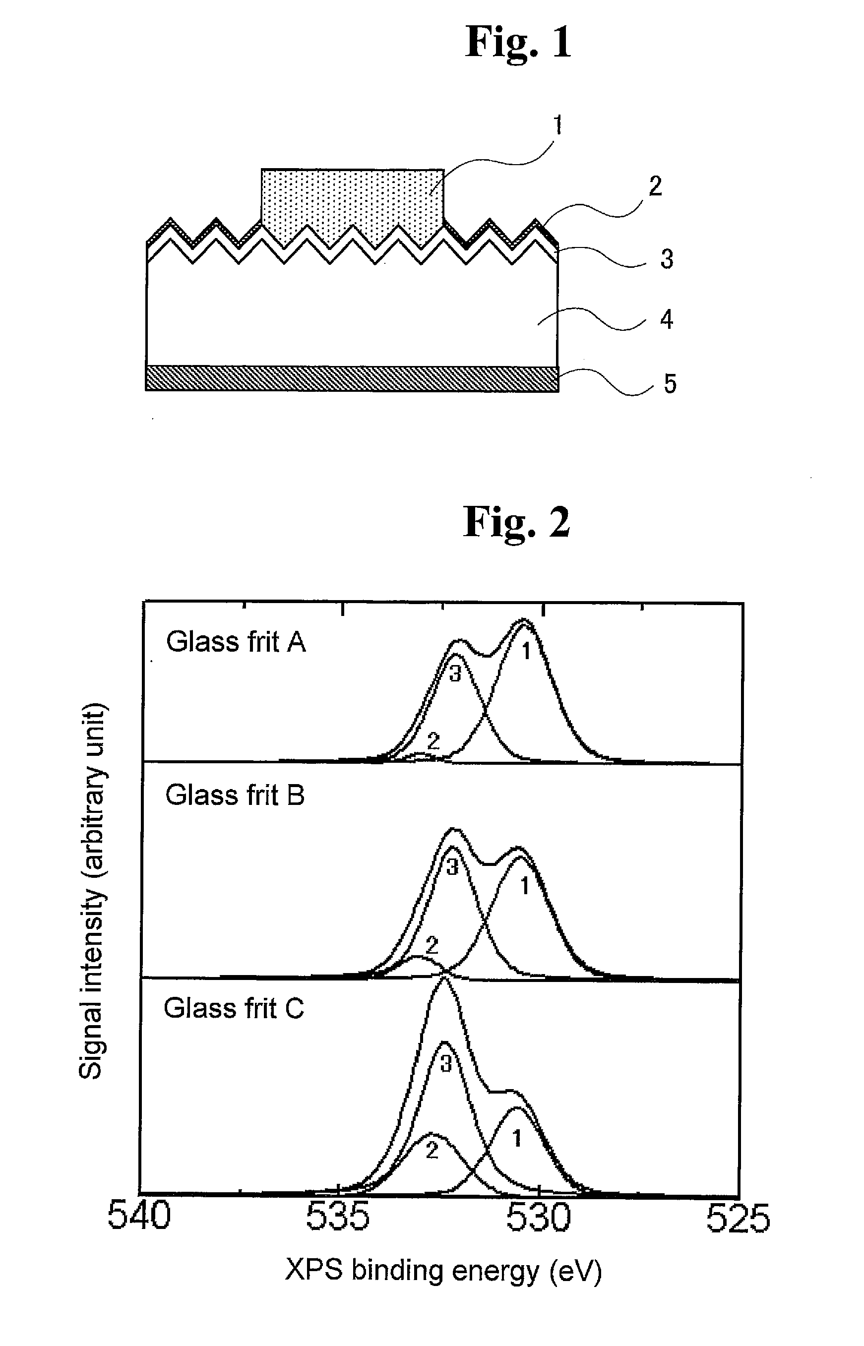
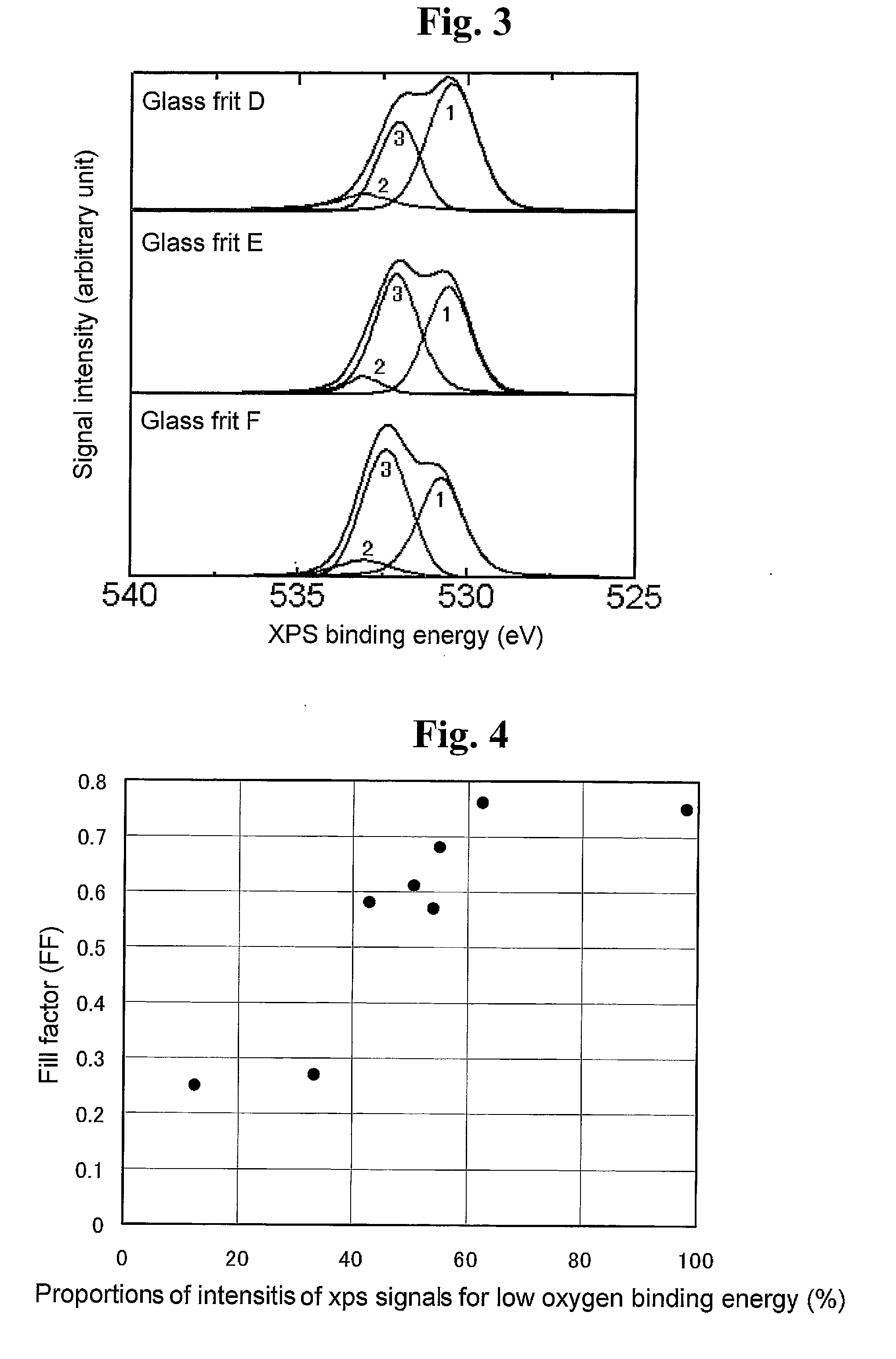
The invention relates to a process for manufacturing solar cells. The manufacturing process of the invention comprises the steps of printing a conductive paste onto an n-type silicon layer of a crystalline silicon substrate or onto an antireflection film on the n-type silicon layer, and drying and firing the conductive paste to form an electrode. The conductive paste comprises a conductive powder, a glass frit and an organic vehicle. The glass frit comprises at least one oxide. X-ray photoelectron spectroscopy of the glass fit gives a spectrum representing binding energies of oxygen in which the signal intensity of a peak with a peak top at a range from 529 eV to less than 531 eV has a proportion of 40% or more relative to the total of signal intensities from 526 eV to 536 eV.

Description

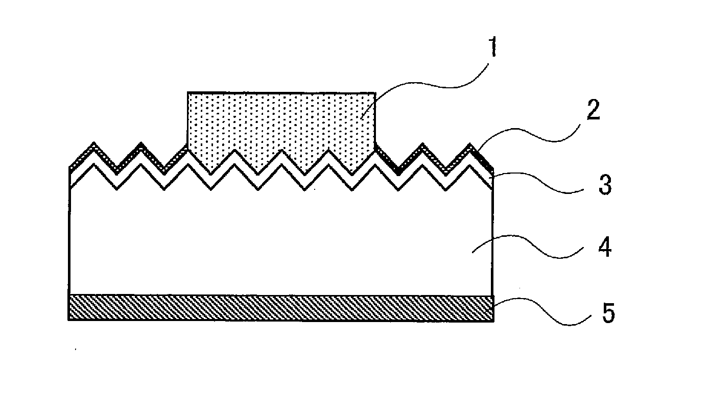
FIELD OF THE INVENTION[0001]The present invention relates to conductive pastes for forming solar cell electrodes, in particular conductive pastes for forming front or back electrodes in crystalline silicon solar cells utilizing crystalline silicon such as monocrystalline silicon and polycrystalline silicon as substrates, to processes for manufacturing solar cells using the conductive pastes for forming an electrode, and to solar cells manufactured by the processes.BACKGROUND OF THE INVENTION[0002]There has recently been a marked increase in the production of crystalline silicon solar cells which utilize plates of monocrystalline or polycrystalline silicon as substrates. Such solar cells have electrodes for output of the generated power.[0003]As an example, a schematic cross sectional view of a crystalline silicon solar cell is illustrated in FIG. 1. In a crystalline silicon solar cell, an n-type diffusion layer (an n-type silicon layer) 3 is generally formed on the light incident si...

Claims


Application Information

Patent Timeline
Patent Type & Authority Applications(United States)
IPC IPC(8): H01L31/0256H01L31/0224H01L31/18
CPCH01L31/0256H01L31/1884H01L31/0224H01L31/022425H01L31/068H01L31/1804Y02E10/547Y02P70/50C03C4/14C03C8/10C03C8/18C03C2204/00C03C2205/00C09D5/24H01L31/022441
Inventor TAKAHASHI, TETSU
Owner NAMICS CORPORATION
Learn More