
Solar cell device and manufacturing method therefor

Active Publication Date: 2011-04-28
HERAEUS PRECIOUS METALS NORTH AMERICA CONSHOHOCKEN +1
View PDF4 Cites 31 Cited by
  • Summary
  • Abstract
  • Description
  • Claims
  • Application Information

AI Technical Summary

Benefits of technology

[0016]It is an object of the present invention to provide a solar cell device having good solar cell characteristics while using a conductive paste not containing lead glass as the conductive paste for a front electrode formation, and to provide a manufacturing method therefor.
[0022]With the present invention, it is possible to obtain a solar cell device having performance and characteristics well comparable with or superior to those of conventional solar cells by forming the electrode using a conductive paste comprising silver as a main component and containing lead-free tellurium glass, without containing any lead glass in the conductive paste as in the past. Because there is little dependence on firing temperature and no problem of deep penetration into the semiconductor substrate by part of the front electrode due to excessive fire-through as in the past, moreover, it is easier to control firing during electrode formation, and the technology can also be applied to making thinner solar cells and thinner n-type diffusion layers.

Problems solved by technology

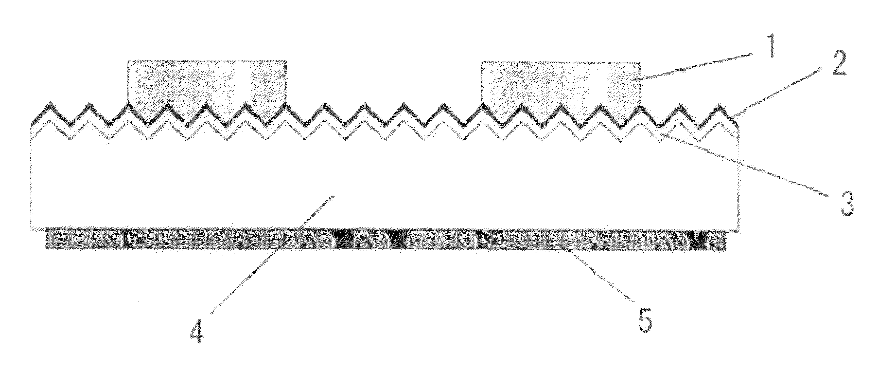
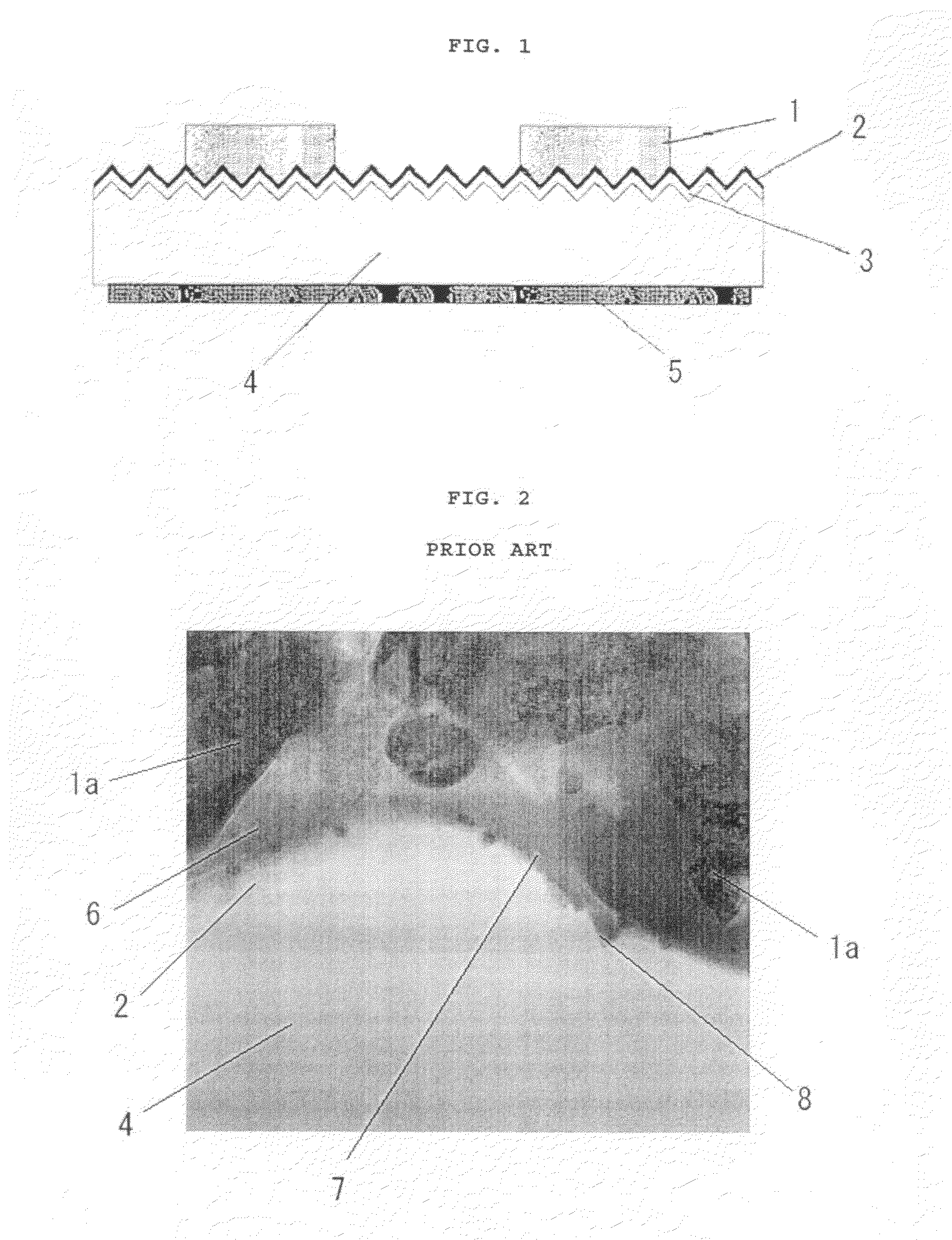
Regarding the aforementioned fire-through, however, problems with variation in adhesive strength and failure to obtain stable ohmic contact between the front electrode 1 and the n-type diffusion layer 3 of the semiconductor substrate 4 have occurred when the front electrode 1 does not penetrate through the antireflective film 2 due to variation in the effect of the glass frit and the like when the front electrode 1 is fired.
Insufficient ohmic contact can cause loss during output, resulting in lower conversion efficiency of the solar cell and a decline in the current-voltage characteristics.
As described in paragraph of Japanese Patent Publication No. 10-326522 A, paragraph of Japanese Patent Publication No. 2004-207493 A, etc, meanwhile, there has been known another problem in which excessive fire-through may also produce inferior voltage characteristics.
Since the antireflective film 2 can be no more than about 5 to 100 nm thick as described above, if the front electrode 1 penetrates through the antireflective film 2 and then through the n-type diffusion layer 3 below to intrude into the semiconductor substrate 4, the p-n junction may be broken, and the fill factor (“FF”) obtained from the current-voltage characteristic measurements may be adversely affected.
In general, tellurium glass is known to have a low melting point, to be highly durable and to easily dissolve silver in solid solution, but it also has extremely low reactivity with silicon oxide, and since silicon-type antireflective films have been popular in recent years, there has been little interest in tellurium glass for forming the front electrodes of solar cells.

Method used


Image

  • Solar cell device and manufacturing method therefor
  • Solar cell device and manufacturing method therefor
  • Solar cell device and manufacturing method therefor

Examples


examples

[0056]The present invention is explained in detail below by means of examples, but the present invention is not limited thereby.

1. Preliminary test

Preparation of Samples 1 to 130

[0057]Glass frit of the compositions shown in Table 1-1 to Table 1-4 in the part or parts (“part(s)” in the tables means the part or parts by weight of the added glass frit) shown in the tables per 100 parts by weight of silver powder was dispersed together with 100 parts by weight of silver powder in an organic vehicle composed of 1.6 parts by weight of ethyl cellulose and 6.4 parts by weight of butyl carbitol, to prepare conductive pastes (Samples 1 to 130). The ingredients in the glass compositions shown in the tables are all given in mol % as oxides.

[0058]The powders listed in the “silver powder” columns in the tables are as follows. The average particle size (D50) shown below corresponds to a weight-based cumulative 50% value in particle size distribution as measured with a laser diffraction particle ...


PUM


Abstract

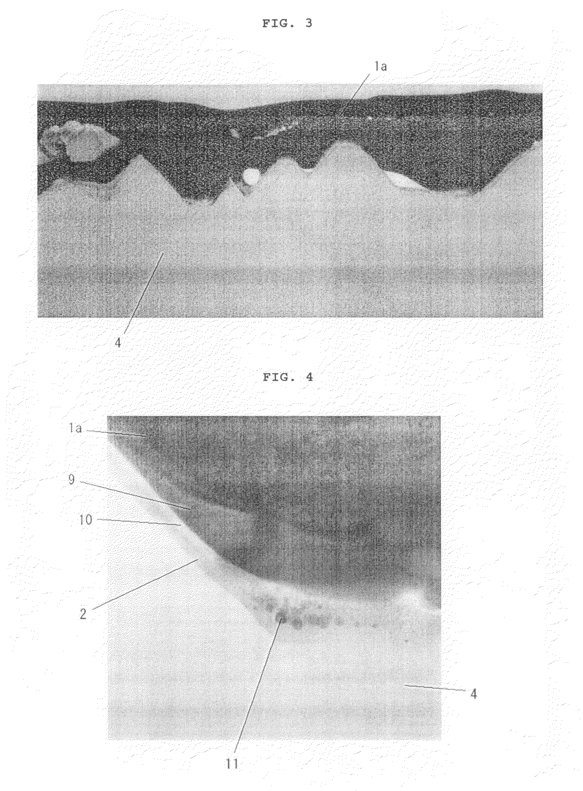
A solar cell device including an electrode formed by applying a conductive paste containing at least a conductive powder, glass frit and an organic vehicle onto a semiconductor substrate provided with a silicon nitride layer on a surface thereof and firing the applied conductive paste, wherein the electrode has a structure comprising a front electrode layer comprising silver as a main component, a glass layer comprising tellurium glass as a main component, and a silicon oxide layer containing plural silver particles precipitated by the firing. The solar cell device is provided with an electrode formed using a conductive paste not containing lead glass and has good solar cell characteristics.

Description

BACKGROUND OF THE INVENTION[0001]1. Field of the Invention[0002]The present invention relates to a solar cell device provided with an electrode formed using a fired-type conductive paste containing glass frit and a conductive powder comprising silver as a main component, and to a manufacturing method therefor.[0003]2. Description of the Related Art[0004]Conventionally, an ordinary solar cell device is provided with a silicon semiconductor substrate, a diffusion layer, an antireflective film, a rear electrode and a front electrode (hereunder sometimes called a “light-receiving electrode”). When forming the front electrode in particular, the electrode is formed by screen printing, stencil printing or the like, using a conductive paste made by mixing conductive particles comprising silver as a main component with glass frit, an organic vehicle, etc.[0005]As one example, in the crystalline silicon solar cell shown in FIG. 1, a diffusion layer 3 is formed in the front surface (light-rece...

Claims


Application Information

Patent Timeline
IPC IPC(8): H01L31/0224H01L31/18
CPCH01L31/022425Y02E10/50Y02E10/52H01B1/22
Inventor AKIMOTO, YUJINAKAMURA, MASAMISHINDO, NAOTOKANASAKU, TADASHI
Owner HERAEUS PRECIOUS METALS NORTH AMERICA CONSHOHOCKEN
Learn More