Eureka AIR delivers breakthrough ideas for toughest innovation challenges, trusted by R&D personnel around the world.

Hydrodynamic slug flow model

a flow model and hydrodynamic technology, applied in the field of hydrodynamic slug flow model, can solve the problems of unavoidable oil and gas production, unstable operation, and disappointment, and achieve the effect of minimal effort and good fit to field data

Inactive Publication Date: 2013-11-28
CONOCOPHILLIPS CO
View PDF3 Cites 28 Cited by
  • Summary
  • Abstract
  • Description
  • Claims
  • Application Information

AI Technical Summary

Benefits of technology

The patent describes a simple model that can produce hydrodynamic slugging from two phases of gas and liquid. This model can reproduce slug flow without the need for a Lagrangian slug tracking scheme. The model can also include a method for producing hydrocarbon containing mixtures from a subterranean formation without slug formation or flow impediments. The technical effect of the patent is to provide a flexible and easy-to-implement alternative for slug flow modeling in hydrodynamic systems.

Problems solved by technology

In addition, water production, either by condensation from saturated gas, or direct production from the reservoir, is an unavoidable aspect of both oil and gas production.
Often, particularly in deepwater operations, there are significant terrain features between the subsea center and the platform, including the platform riser, which could result in unstable operation.
Even in instances where the individual slugs are introduced and tracked in a Lagrangian frame, so-called ‘slug tracking’ (Bendiksen, 1990), the results have been somewhat disappointing, in that the ultimate slug distributions are heavily influenced by user input.
While such models were quite successful in simulating hold-up and pressure drop during both steady-state and transient operations, many associated flow assurance issues (e.g., hydrates, hydrodynamic slugs) remain quite rudimentary.
Also, the simulators themselves are terrifically slow by general computational fluid dynamics (CFD) standards.
Lastly, particularly in long transportation pipelines, heat loss to the ambient surroundings actually drives such processes as paraffin deposition on the pipe wall.
Thus, all flow assurance issues occur against the backdrop of multiphase flow.
One such example is corrosion.
In annular flow, sand can be carried in the gas phase at high rates, leading to erosion failures.
The Taitel-Dukler criterion has proved fairly accurate against low-pressure, air-water data, but does not capture the stratified-slug boundary accurately for higher pressures (Taitel and Dukler, 1990).
While the minimum slip criteria has proven quite accurate at high pressures, there is evidence to suggest that it does not accurately capture flow regime when benchmarked against low-pressure, air-water data, or for data with significant negative inclinations.
Transient two-phase flow is incredibly complex.
This large number of dimensionless groups points to the inherent complexity of the phenomenon.
Unfortunately for the modeler, the presence of a third phase complicates the models considerably.
This is ‘almost always’ good enough to handle most situations of relevance for flow assurance'; however, there are phenomena which cannot be captured (for example, oil / water slugging) which require that water have its own momentum equation.
Unfortunately, the two approaches are fundamentally the same and have similar faults and computational requirements.
Thus, anywhere there is even a small amount of liquid present, it tends to alter the Joule-Thompson cooling characteristics, and thus the temperature transient behavior, of the gas-liquid mixture.
Given that cold gas in the presence of water can result in hydrate formation, either during shutdown or just after restart, this suggests that a single-equation, mixture-energy approach may be inadequate from a flow assurance point of view.
It is the author's view that while look-up tables were a very clever stop-gap measure that was—at one time—necessary, the concept has probably outlived its usefulness.
Generally, experimental equipment available in university laboratories are limited to air-water experiments at near-atmospheric conditions in 1-2 inch pipe; this severely limits the scalability of the models produced.
There are many drawbacks in the two-fluid, two-momentum equations approach.
First, the interfacial shear stress term τ1 cannot be measured directly, even in principle.
Second, the interfacial surface area S1 is difficult to define except for the degenerate case of stratified-smooth flow in horizontal pipe.
However, they involve terms such as the ‘interfacial friction factor’, which cannot be measured directly, and must be inferred from the experimental data.
The presence of multiple flow regimes greatly complicates the formulation of a transient multiphase model.
For example, there may be discontinuities in both hold-up and pressure drop across flow regime boundaries (a non-issue in steady-state codes) which could introduce numerical instabilities or convergence problems in the transient code.
Unfortunately, the drift-flux model fails at low liquid superficial velocities (see e.g. Danielson and Fan 2009).
Because of the large amount of sub-grid calculations that a transient multiphase flow simulator must make, compared to a general CFD code, the performance of transient multiphase flow codes is quite slow by comparison.

Method used


Image

  • Hydrodynamic slug flow model
  • Hydrodynamic slug flow model
  • Hydrodynamic slug flow model

Examples


example 1

Stability Analysis

[0130]The stability of these ‘steady-state’ solutions can be examined through the application of mass conservation for a particular point in the pipeline. The mass conservation equation for the liquid phase is given by:

d(ρL δz·A·HL) / dt=(ρL·A·USL)IN−(ρL·A·USL)OUT

If the liquid density, pipe cross-sectional area, and section length are constant, this simplifies to a volume conservation equation:

δz·d(HL) / dt=(USL)IN−(USL)OUT

Consider a single cell, with a constant inlet superficial velocity (USL)IN, with (USL)OUT as a function of the hold-up in that cell:

USL(HL)≡US(HL)HL2+(UM−US(HL))HL

Note that the hold-up equation is used not to determine the hold-up from the superficial velocities and the slip velocity; now the superficial velocity is determined from the hold-up, the slip velocity, and the mixture velocity. The volume conservation equation can be written as:

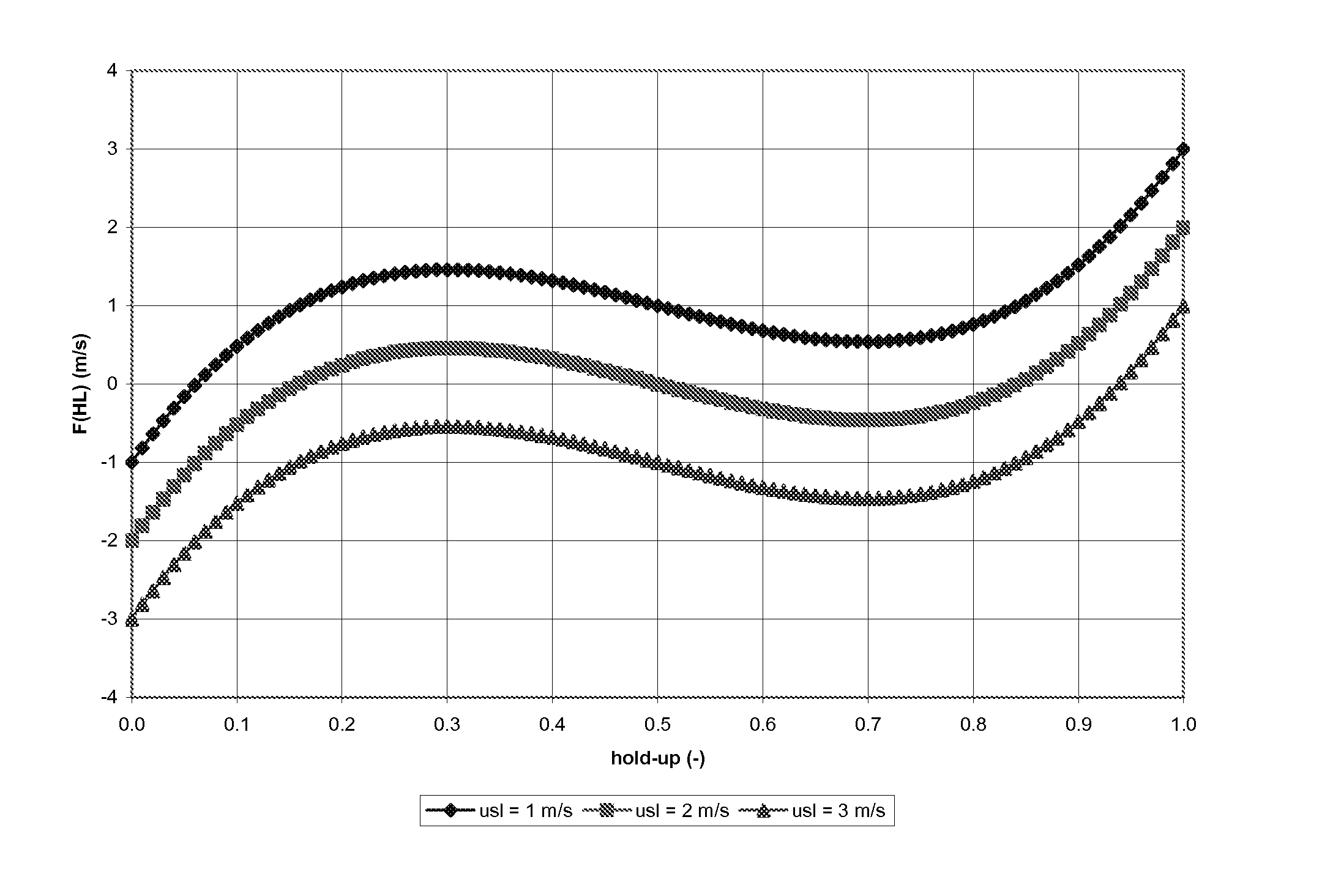
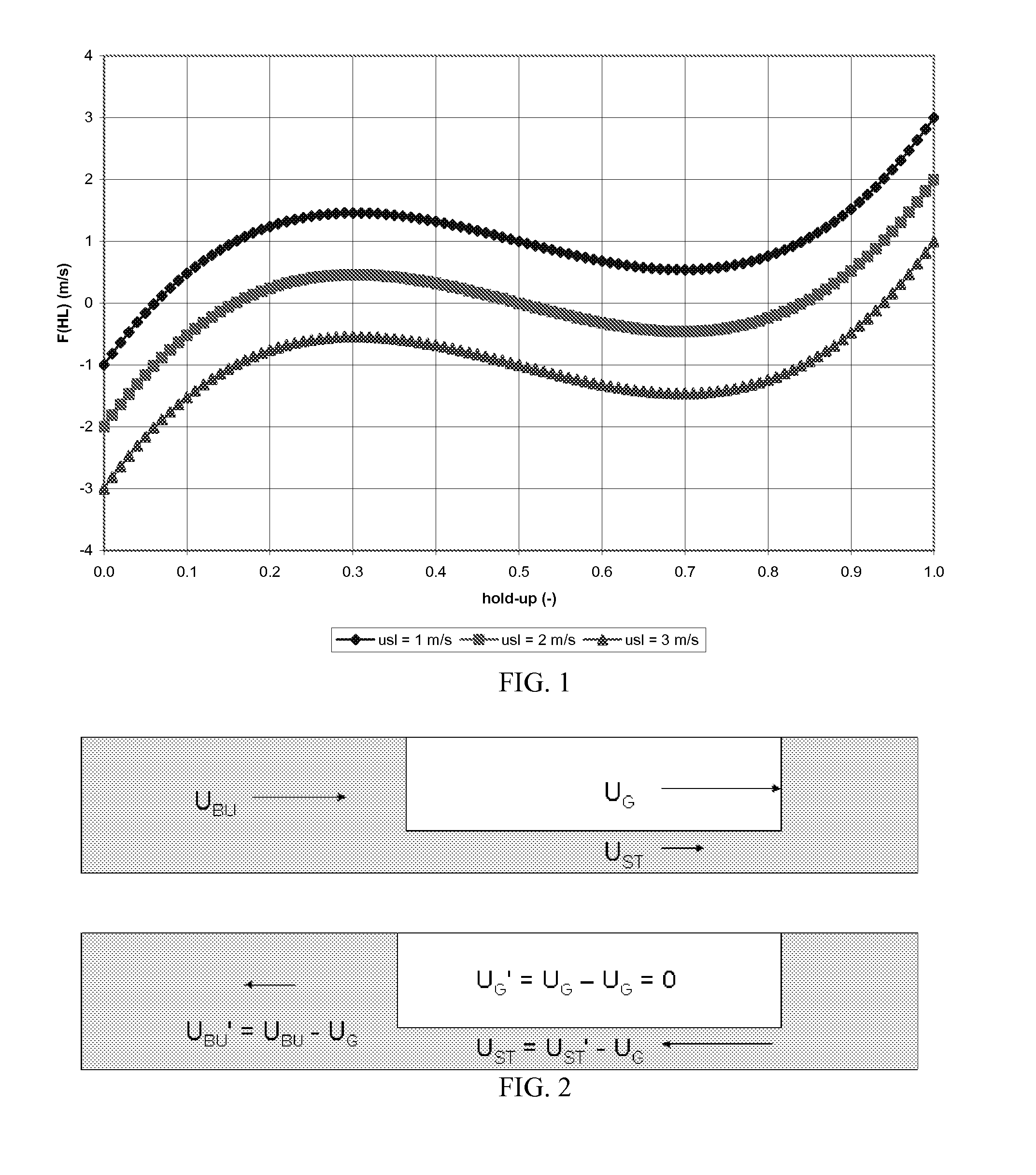
δz·d(HL) / dt=USL−[hd S(HL)HL2+(UM−US(HL))HL]=−F(HL)

Let HL* be a zero of F(HL) and therefore a solution to the h...

example 2

Multiple Solutions

[0131]Of course, it is entirely possible that the hold-up function F(HL) can cross the hold-up axis at more than one point, i.e., F(HL) can have more than 1 physically-realizable solution. In fact, if F(HL) is a continuous function of HL, any odd solutions is at least topologically possible (even numbers of crossings are not possible if USL, USG>0).

[0132]If the slip velocity US is constant, then F(HL) is quadratic in hold-up. Since a quadratic equation can only have, at most—2 real roots, there can only be a single crossing between 0LL=0)L=1)>0.

[0133]Hydrodynamic slug flow is characterized by high-hold-up slugs of liquid with little slip between the gas and liquid phases separated by low-hold-up stratified regions characterized by high slip between the phases. The gas bubble in the separated region travels at a characteristic speed UG which can be related to mixture velocity via a ‘drift-flux’ relation:

UG=CO·UM+UO

The slip velocity is given by:

US=(UG−UM) / HL=[(CO−1)...

example 3

Change of Reference Frame

[0142]Although the cubic form of F(HL) has many appealing properties, there is one last step that must be addressed in order to formulate our transient slug model. While it is true that the superficial velocities in slug flow are not all equal in a reference frame that is fixed with the pipe, in a moving reference frame they can—in fact—be made to be equal. Consider FIG. 2, which shows slug flow in a fixed frame, and also from a reference frame which moves at the velocity of the gas bubble in the stratified region, UG. The linear velocities in the new reference frame are:

UBU′=UBU−UG; UST′=UST−UG

Obviously, the hold-ups are not a function of reference frame; however, the superficial velocities are. This can be seen by the following:

USBU′ / HB=USBU / HB−UG→USBU′=USBU−UG·HB; USST′ / HS=USST / HS−UG→USST′=USST−UG·HS

Finally, as a consequence of the above:

UM′=UM−UG

In the moving reference frame, USBU′=USST′=UM′, by definition. The gas velocity UG can be calculated from a...


PUM


Abstract

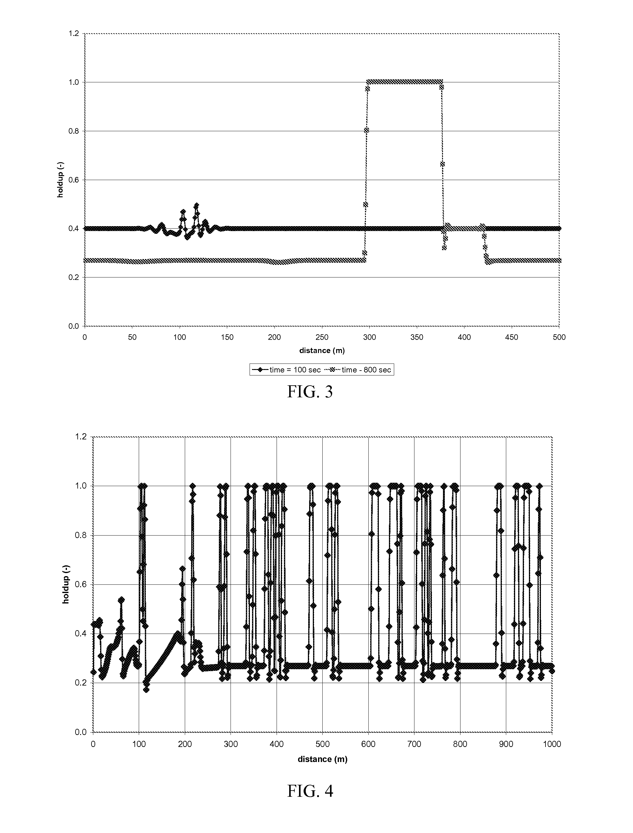
A very simple model has been presented which is able to reproduce slug flow from the instability of a flow with average hold-up and slip. The disclosure demonstrates that slug flow may be modeled as two different, stable solutions to the multiphase flow which coexist at different points in the line, moving with a celerity of UG. By using a white-noise inlet condition which preserves the average hold-up in the pipeline, a series of stable slug and stratified regions can be created without any need to resort to a Lagrangian slug tracking scheme. A quite good fit to field data was obtained with minimal effort by adjusting the slip relation. At present, the model merely demonstrates a potential, very attractive, flexible, and easy-to-implement alternative to Lagrangian slug tracking.

Description

CROSS-REFERENCE TO RELATED APPLICATIONS[0001]This application is a non-provisional application which claims benefit under 35 USC §119(e) to U.S. Provisional Application Ser. No. 61 / 638,794 filed Apr. 26, 2012, entitled “HYDRODYNAMIC SLUG FLOW MODEL,” which is incorporated herein in its entirety.STATEMENT REGARDING FEDERALLY SPONSORED RESEARCH[0002]None.FIELD OF THE INVENTION[0003]Hydrodynamic slug flow is the prevailing flow regime in oil production, yet industry still lacks a comprehensive model, based on first principles, which fully describes hydrodynamic slug flow. In one embodiment, a very simple model has been presented which is able to reproduce slug flow from the instability of a flow with average hold-up and slip. The disclosure demonstrates that slug flow may be modeled as two different, stable solutions to the multiphase flow which coexist at different points in the line, moving with a celerity of UG. By using a white-noise inlet condition which preserves the average hold...

Claims


Application Information

Patent Timeline
Patent Type & Authority Applications(United States)
IPC IPC(8): G06F17/50
CPCG06F17/5009G06F2111/10G06F30/20
Inventor DANIELSON, THOMAS J.
Owner CONOCOPHILLIPS CO
Why Eureka
Eureka Blog
Learn More