Device for supplying a reducing agent to an exhaust-gas aftertreatment system

a technology of exhaust gas aftertreatment and reducing agent, which is applied in the direction of machines/engines, mechanical equipment, transportation and packaging, etc., can solve the problems of preventing the freezing of the fill level sensor, requiring and the device for measuring the surface level of the vessel requires an extremely large amount of technical investment. , to achieve the effect of preventing measurement errors, simplifying structural design, and improving suctioning behavior

Inactive Publication Date: 2013-12-05
ROBERT BOSCH GMBH
View PDF4 Cites 17 Cited by
  • Summary
  • Abstract
  • Description
  • Claims
  • Application Information

AI Technical Summary

Benefits of technology

[0030]This yields a further simplification of the structural design, because the fill level sensor approximately coaxially surrounds the suctioning line and the at least two cables. Before the electrical supply cables and the suctioning line are drawn into the fill level sensor, it may be advantageous for both the cables and also the suctioning line to be combined at least in portions, so as to form a bundle or a strand-like entity, by means of an additional casing.
[0031]The fill level sensor preferably has at least one vent, in order to prevent measurement errors during the determination of the fill level. The vent of the fill level sensor is preferably arranged at the same height as or higher than the tank vent.
[0032]A further embodiment of the device provides that the pump sump is arranged in the region of an elevation or of a depression of the tank base. In this way, the suctioning behavior can be further improved in particular in the case of low reducing agent surface levels in the tank.

Problems solved by technology

Since the fill level sensor does not have a direct heating device, it cannot be ruled out that said fill level sensor will freeze, in particular in the event of frost temperatures prevailing over a long period of time.
In the event of extreme oblique positions of the tank, however, the ice pressure resistance cannot be ensured because the air cushion can at least partially escape out of the space delimitation means.
Said device for measuring a vessel surface level however requires an extremely large amount of technical outlay.
Excessive tilting of the vessel or freezing of the liquid at least in regions, however, can under some circumstances influence the measurement result.

Method used


Image

  • Device for supplying a reducing agent to an exhaust-gas aftertreatment system
  • Device for supplying a reducing agent to an exhaust-gas aftertreatment system
  • Device for supplying a reducing agent to an exhaust-gas aftertreatment system

Examples


Embodiment Construction

[0043]FIG. 1 is a schematic illustration of the device according to the invention.

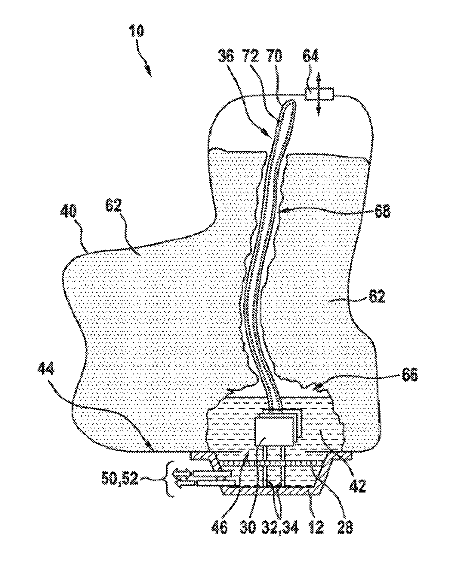
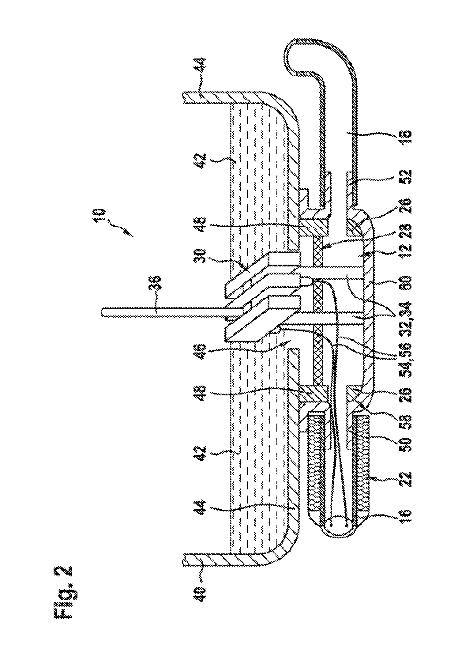
[0044]The device 10 comprises inter alia an approximately pot-shaped pump sump 12 which is connected to a delivery module 14 via a heated and ice-pressure-resistant suctioning line 16. By contrast to the pot-shaped form of the pump sump 12 shown in the example, said pump sump may for example also have the geometric form of an internally hollow truncated cone portion with a distinctly oblique encircling wall. To the pump sump 12 there is connected a fill level sensor 18 which has, at its upper end, a vent 20. To minimize the heat losses, both the heated suctioning line 16 and also the fill level sensor 18 are completely surrounded by an insulation sheathing 22. The pump sump 12 is fastened in the region of a tank opening on the underside of a tank not illustrated in FIG. 1. The tank serves for storing the reducing agent required for carrying out the SCR method. As reducing agent for the SCR method, use ...


PUM


Abstract

The invention relates to a device (10) for supplying to an exhaust-gas aftertreatment system a reducing agent (42), in particular a urea-water solution for the reduction of nitrogen oxides in the exhaust-gas flow of a diesel engine, having a tank (40) for the reducing agent (42) and having a delivery module (14) for delivering the reducing agent (42) out of the tank (40) via an in particular electrically heatable suction line (16). According to the invention, a) the suction line (16) which runs outside the tank (40) is connected to a pump sump (12) situated in the region of the tank base (44), b) an in particular electrically operated pump sump heater (30) is arranged in the region of the pump sump (12), c) at least one in particular electrically operated heating rod (36) extends into the tank (40), and d) at least one fill level sensor (18) runs outside the tank (40). The pump sump heater (30), the heated suction line (16), the heating rod (36) and an optional elastic compensating element (26) in the region of the pump sump (12) permit a substantially temperature-independent supply of the reducing agent (42) to an exhaust-gas aftertreatment system of a diesel engine. The pump sump (12) which is mounted on the bottom of the tank (40) furthermore makes it possible for the reducing agent (42), which must be available in the exact dose for correct execution of the SCR method, to be supplied virtually completely independent of position, and nevertheless uniformly, to the exhaust-gas aftertreatment system.

Description

BACKGROUND OF THE INVENTION[0001]In motor vehicles with internal combustion engines, in particular diesel engines, it is necessary, owing to the ever more stringent legal exhaust-gas limit values, to further reduce inter alia air pollutants such as for example nitrogen oxides (NOx), in the exhaust-gas flow. A widely used method which is applied here is catalytic reduction, that is to say the so-called SCR method (“Selective Catalytic Reduction”). Here, during the operation of an internal combustion engine, in particular of a diesel engine, a liquid reducing agent is delivered by means of a pump from a storage vessel to a dosing module with an injection nozzle in the region of a catalytic converter in the exhaust pipe. As reducing agent, use is generally made of a 32.5% urea-water solution, which is marketed under the trade name “AdBlue®”. In this connection, it must be taken into consideration that said urea-water solution freezes at a temperature below −11° C., and thermally decomp...

Claims


Application Information

Patent Timeline
Patent Type & Authority Applications(United States)
IPC IPC(8): F01N3/20
CPCF01N3/208F01N3/2066F01N2610/02F01N2610/10F01N2610/1406B60K13/04B60K2015/03427Y02A50/20Y02T10/12
Inventor GOTTWALD, FRANK
Owner ROBERT BOSCH GMBH
Why Eureka
Try Eureka