
Method and Apparatus for Material Densification

Inactive Publication Date: 2013-12-05
ALTEX TECH
View PDF5 Cites 12 Cited by
  • Summary
  • Abstract
  • Description
  • Claims
  • Application Information

AI Technical Summary

Benefits of technology

The patent describes a method for compressing and heating lignocellulosic biomass to produce durable logs with low surface area per volume, low energy requirements, and high strength and structural integrity. The method involves compressing the biomass into logs using a baler or other equipment, and then heating them to activate a binder material that strengthens the logs. The resulting logs have a protective shell formed by the binder material, which further reduces friction and power requirements. The method also allows for separate control over the compression and heating phases, and can increase production throughput by preheating the material before moving it into the main heating section. The compactor used in the method has a continuous heating and cooling section, a variable load and speed compacting piston, and a heated gate for compaction of material.

Problems solved by technology

Drying and sizing are two high energy consumption processes.
In breaking the material down, any benefit of the original biomass structural integrity is lost, and this has to be replaced by adding a binder to hold the biomass particles together once they are forced out of the die by high pressure.
In addition a lot of heat energy is required for activating the inherent binder or externally added binder.
Frictional heating is wasteful, since the expensive electric power driving the machine is the source of heat.
Therefore, these processes are high energy consuming processes, which result in high production costs for densified biomass.
This excessive energy to heat all of the material further increases the production cost of densified biomass.
This forced external cooling further increases the cost of production of densified material.
Furthermore, since cooling and setting of the binder occurs after discharge of the material from the machine, the material can springback or lose some densification in the cooling process.

Method used


Image

  • Method and Apparatus for Material Densification
  • Method and Apparatus for Material Densification
  • Method and Apparatus for Material Densification

Examples


Embodiment Construction

[0040]The discussion proceeds as follows. Preferred embodiments of a system and process for densification of biomass material are discussed first with reference to FIGS. 1-7. Next, laboratory experiments are discussed. These experiments were done to make preliminary estimates of process parameters, such as heating and cooling times, for logs. Next discussed is a full-scale field test of a compactor for biomass material. From the field test conclusions are reached regarding the various parameters associated with the densification process and modifications, types of material, etc.

[0041]FIGS. 1-7 depict a compactor and steps associated with the densification of a lignocellulosic biomass material according to the disclosure. The compactor receives the lignocellulosic biomass material in the form of a bale and converts the bale into a compacted, densified form which, for the sake of convenience shall be called a log. The term “log” is not intended to be limiting as to its final form. Rat...


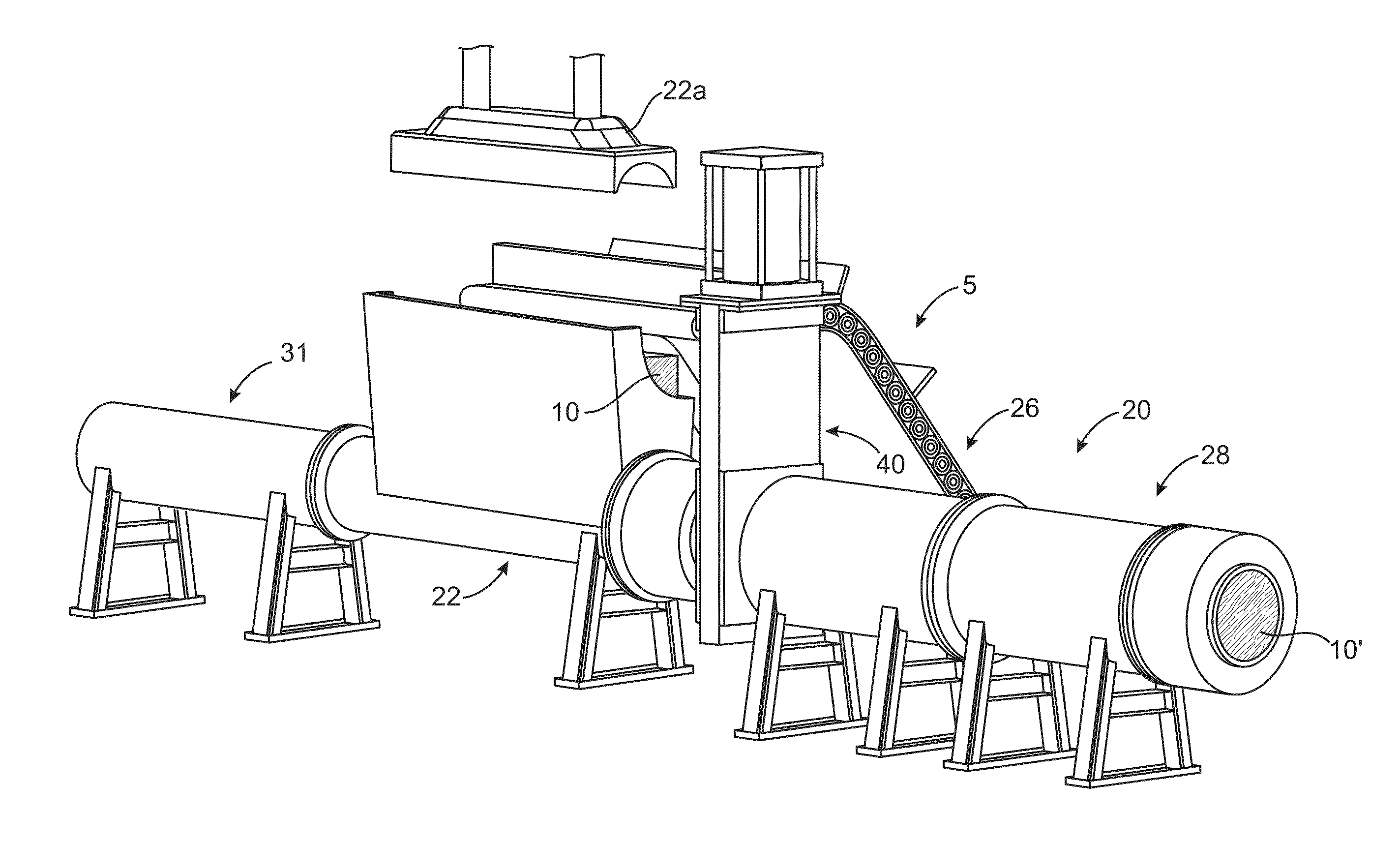
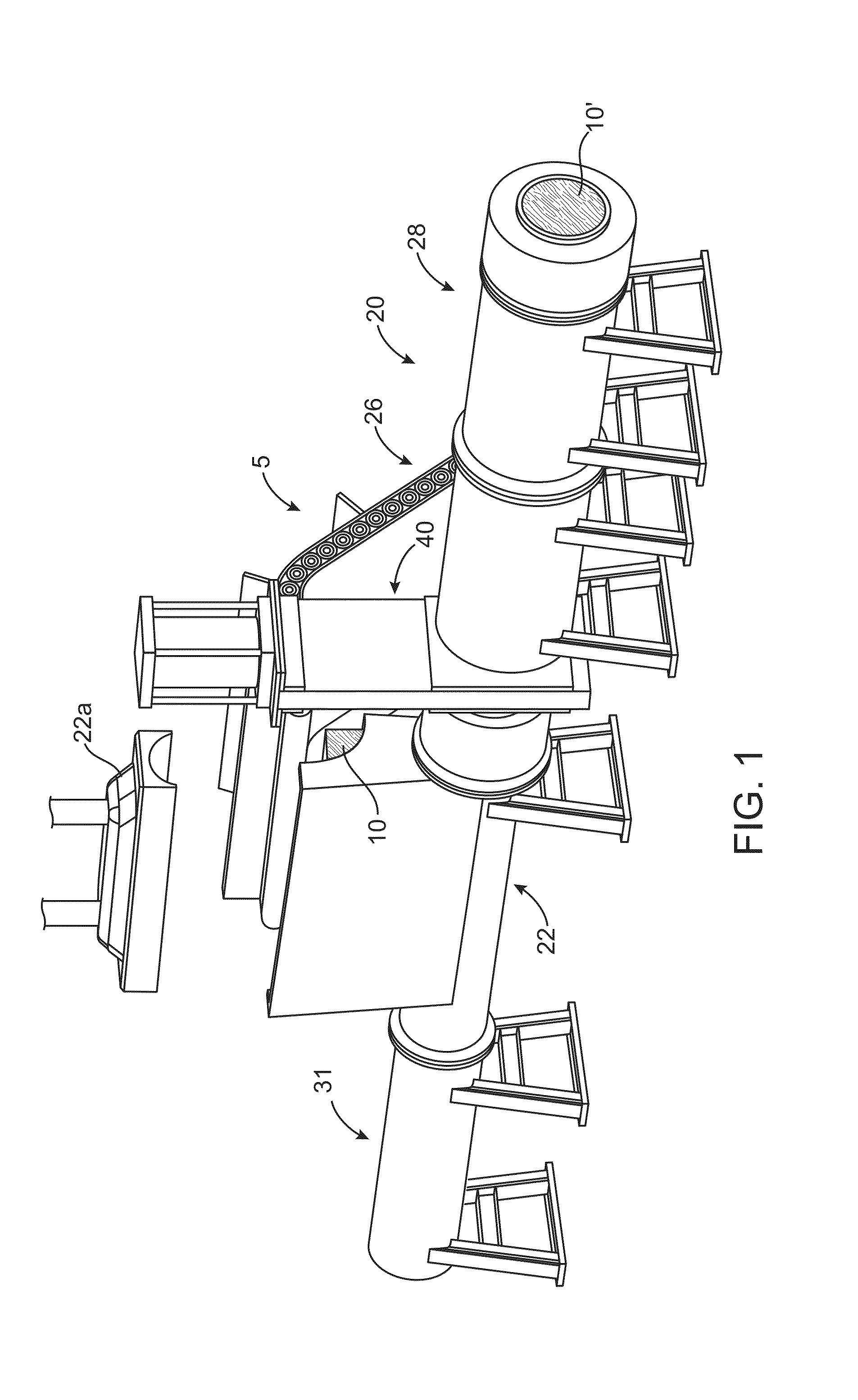
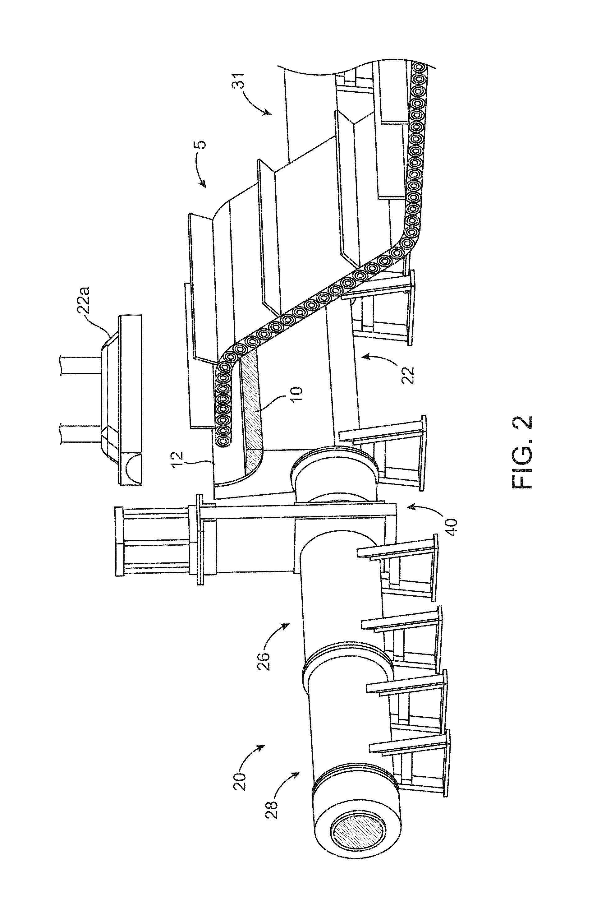
PUM

PropertyMeasurementUnit
Massaaaaaaaaaa
Massaaaaaaaaaa
Timeaaaaaaaaaa

Abstract

A process and apparatus for densification of material compresses the material, then heats and cools the compressed material to provide structural integrity and durability to the resultant densified product. For a lignocellulosic biomass material an inherent binder is used. The binder is activated substantially only along the periphery of the compressed material to increase throughput and reduce energy used during the densification process.

Description

[0001]The invention was made with Government support under DE-FG02-08ER85187 awarded by the Department of Energy (DOE). The Government has certain rights in the invention.FIELD OF THE INVENTION[0002]The present invention relates to densification of material, such as lignocellulosic biomass.BACKGROUND OF THE INVENTION[0003]Densification is an important unit operation involved in utilization of initially lower density material, because it reduces handling, storage and transportation costs. Lignocellulosic biomass material is one material type that benefits from densification. At present, biomass is densified for production of Solid Fuel (eg. Wood pellets) used in stoves for heating in the US and elsewhere, for use in utility (pulverized coal firing) and industrial boilers (stokers firing lumps 0.5 inches in diameter) and in the co-firing of coal and biomass in power plants to achieve renewable goals. Animal feed materials such as Alfalfa and others are also densified to lower transpor...

Claims


Application Information

Patent Timeline
IPC IPC(8): C10L5/10B30B15/34C10L5/44
CPCB30B11/04B30B15/34C10L5/44Y02E50/10Y02E50/30C10L5/365C10L5/445B30B11/025
Inventor KELLY, JOHN T.CHEVANAN, NEHRUMILLER, GEORGE RAYMOND
Owner ALTEX TECH
Learn More