Inspection system using scanning electron microscope

a scanning electron microscope and inspection system technology, applied in the field of inspection systems, can solve the problems of difficult observation of the image of the object to be inspected, the size of the specimen to be observed by a contemporary sem, and the use of such a vacuum scanning electron microscope is difficult for purposes, so as to reduce the influence of external noise on the inspection system, the effect of yield improvemen

Active Publication Date: 2013-12-05
SAMSUNG DISPLAY CO LTD
View PDF21 Cites 42 Cited by
  • Summary
  • Abstract
  • Description
  • Claims
  • Application Information

AI Technical Summary

Benefits of technology

[0028]According to the present invention, the object to be inspected of a larger size may be inspected for the analysis without damage to the object to be inspected such that a cost reduction and a yield improvement may be realized.
[0029]Also, the object to be inspected is positioned in the atmospheric conditions such that the image distortion of the object to be inspected by the charging effect generated in the vacuum chamber is prevented and the object to be inspected is not co

Problems solved by technology

The size of a specimen to be observed by a contemporary SEM is limited by the size of a vacuum chamber of the SEM.
A vacuum scanning electron microscope that is capable of observing a semiconductor wafer fabricated up to 30 inches in width has been developed; however, usage of the such a vacuum scanning electron microscope is difficult for purposes such as conducting an inspection of the flat panel display devices of the size from 730 mm×920 mm to 2200 mm×2500 mm due to the size limitations on the vacuum chamber of the SEM.
When the size of the vacuum chamber

Method used


Image

  • Inspection system using scanning electron microscope
  • Inspection system using scanning electron microscope
  • Inspection system using scanning electron microscope

Examples


Embodiment Construction

[0037]The present invention will be described more fully hereinafter with reference to the accompanying drawings, in which exemplary embodiments of the invention are shown. As those skilled in the art would realize, the described embodiments may be modified in various different ways, all without departing from the spirit or scope of the present invention.

[0038]Descriptions of parts not related to the present invention are omitted, and like reference numerals designate like elements throughout the specification.

[0039]Thus, an inspection system using a scanning electron microscope according to an exemplary embodiment will be described with reference to FIG. 1 to FIG. 5.

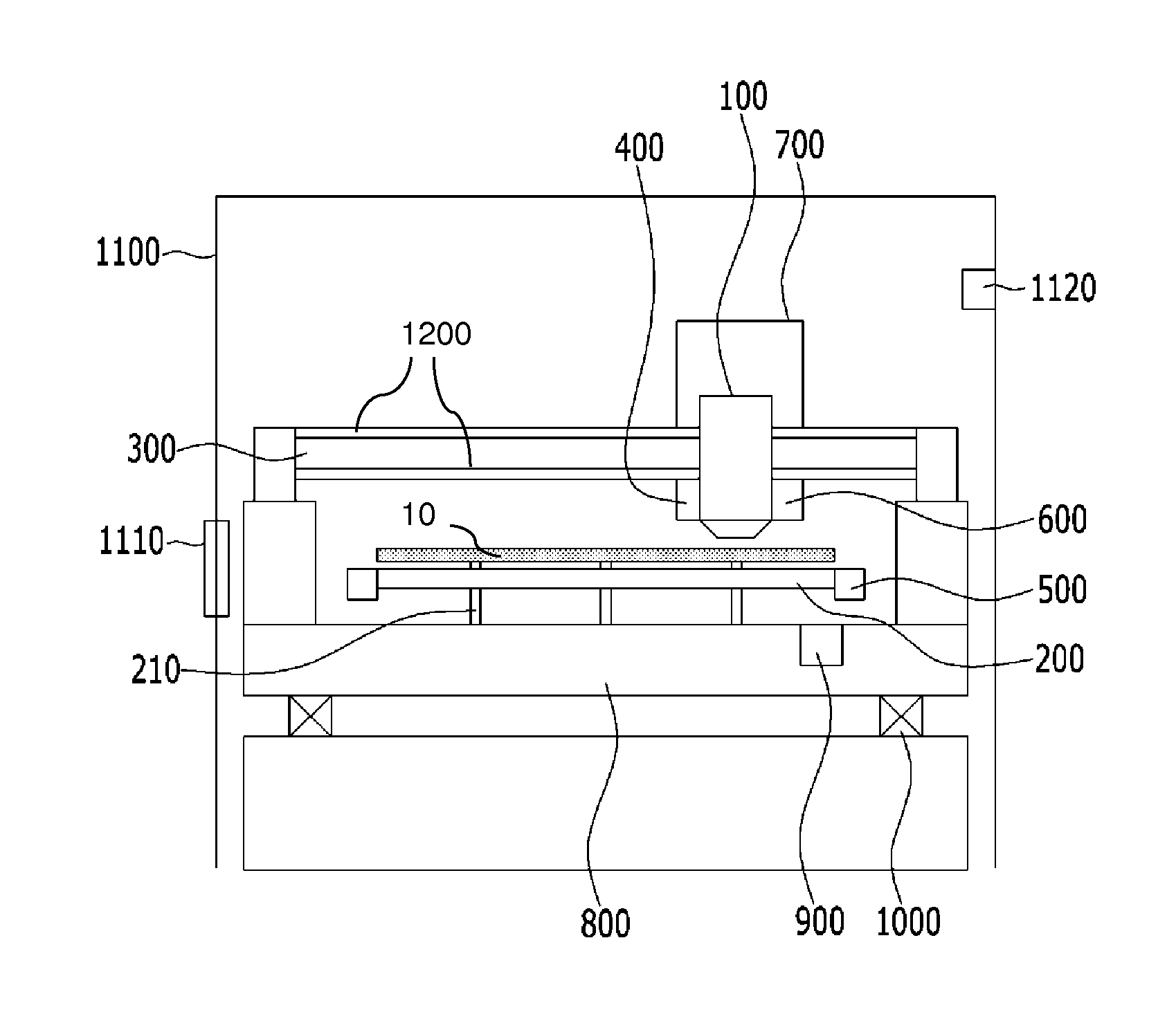
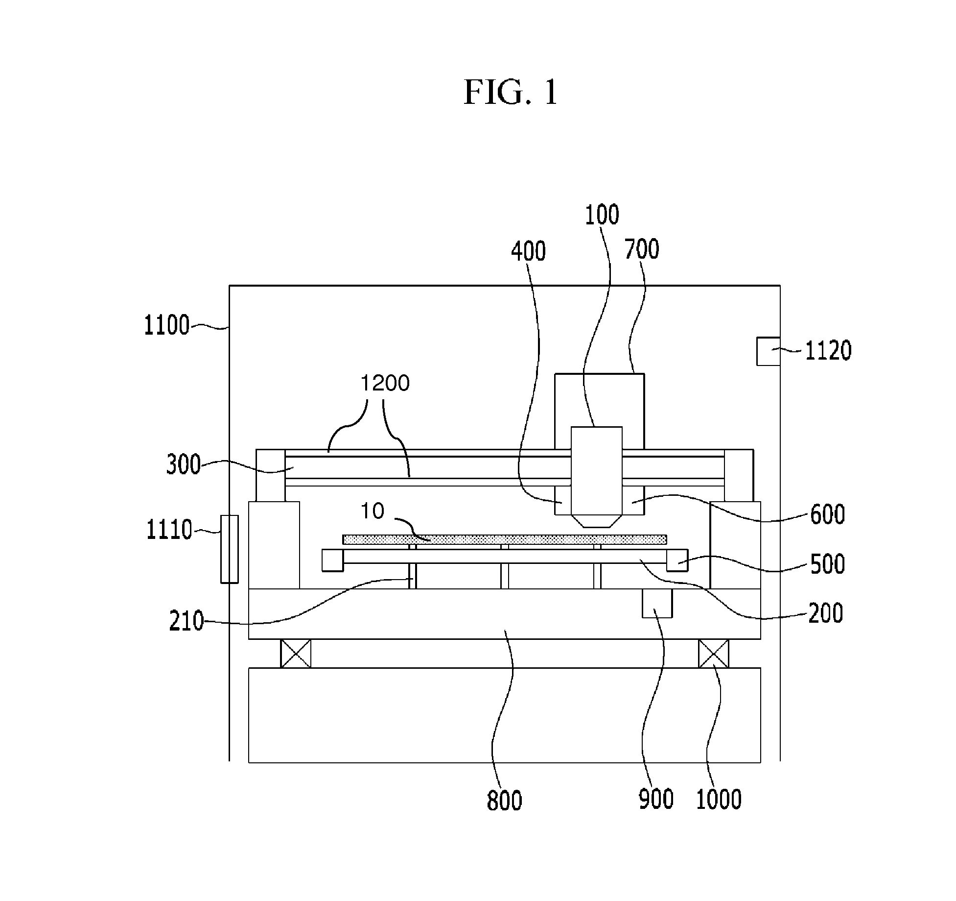
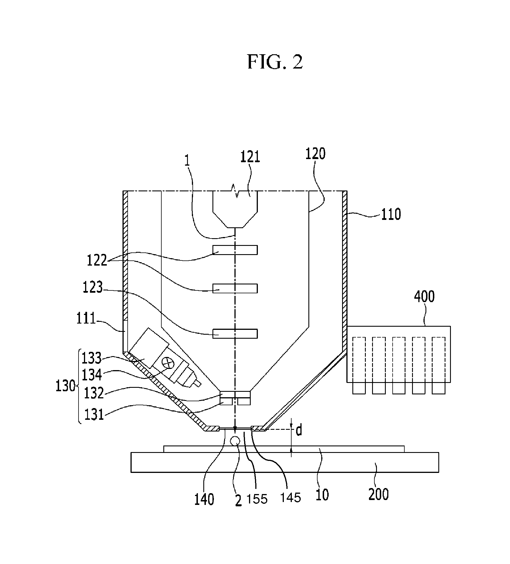
[0040]FIG. 1 is a schematic diagram of an inspection system using a scanning electron microscope according to an exemplary embodiment, FIG. 2 is an enlarged view of a scanning electron microscope chamber and a stage of an inspection system using a scanning electron microscope according to an exemplary embodiment, FIG. 3...


PUM


Abstract

An inspection system using a scanning electron microscope includes a scanning electron microscope chamber inspecting an object to be inspected by using an electron beam and maintaining a vacuum condition, a stage positioned below the scanning electron microscope chamber to be separated therefrom and mounted with the object to be inspected, and a transverse guide transferring the scanning electron microscope chamber on the stage. Atmospheric conditions are maintained between the scanning electron microscope chamber and the object to be inspected. Accordingly, object to be inspected a large size of an object to be inspected may be inspected without damage to the object to be inspected such that a cost reduction and a yield improvement may be realized.

Description

CLAIM OF PRIORITY[0001]This application makes reference to, incorporates the same herein, and claims all benefits accruing under 35 U.S.C. §119 from an application earlier filed in the Korean Intellectual Property Office on May 30, 2012 and there duly assigned Serial No. 10-2012-0057468.BACKGROUND OF THE INVENTION[0002]1. Field of the Invention[0003]The present invention relates generally to an inspection system that uses a scanning electron microscope, and more particularly, to an inspection system that uses a scanning electron microscope to perform inspections of an object under atmospheric conditions without limitation of the size of the object.[0004]2. Description of the Related Art[0005]In general, flat panel display devices such as liquid crystal display (LCD) devices and organic light emitting diode (OLED) display devices are formed by depositing a plurality of thin films and wires on a substrate. In order to inspect for the existence of imperfections such as impurities or pa...

Claims


Application Information

Patent Timeline
IPC IPC(8): H01J37/26
CPCH01J37/26H01J37/185H01J37/20H01J37/28H01J2237/24592H01J2237/2605G02B21/00
Inventor PARK, YOUNG-GILBAEK, WON-BONGOH, KI-WON
Owner SAMSUNG DISPLAY CO LTD
Why Eureka
Try Eureka