
Thin film transistor, thin film transistor array panel including the same, and manufacturing method thereof

a technology of thin film transistors and array panels, which is applied in the direction of diodes, semiconductor devices, electrical devices, etc., can solve the problems of low charge mobility, increase manufacturing time and cost, and manufacturing a high-performance thin film transistor, and achieve the effect of reducing the kickback voltag

Active Publication Date: 2013-12-05
SAMSUNG DISPLAY CO LTD
View PDF32 Cites 42 Cited by
  • Summary
  • Abstract
  • Description
  • Claims
  • Application Information

AI Technical Summary

Benefits of technology

The present invention improves the performance of thin film transistors (TFTs) that use oxide semiconductors. The invention reduces a problem called "kickback voltage" caused by parasitic capacitance between the TFT's gate electrode and its source or drain region. This reduces signal delay and distortion in the TFT array panel, resulting in improved performance of the overall display.

Problems solved by technology

The silicon can be divided into amorphous silicon and polysilicon according to a crystallization type, wherein the amorphous silicon has a simple manufacturing process, but has low charge mobility such that there is a limit in manufacturing a high performance thin film transistor using the amorphous silicon, while the polysilicon has high charge mobility, but additional, complicated processes of crystallizing the polysilicon may be required, thereby increasing the manufacturing time and cost.
However, if parasitic capacitance is generated between the gate electrode and the source electrode or the drain electrode of the thin film transistor, a characteristic of the thin film transistor as the switching element may be deteriorated despite the above various approaches.

Method used


Image

  • Thin film transistor, thin film transistor array panel including the same, and manufacturing method thereof
  • Thin film transistor, thin film transistor array panel including the same, and manufacturing method thereof
  • Thin film transistor, thin film transistor array panel including the same, and manufacturing method thereof

Examples


Embodiment Construction

[0037]The present invention will be described more fully hereinafter with reference to the accompanying drawings, in which exemplary embodiments of the invention are shown. As those skilled in the art would realize, the described embodiments may be modified in various different ways, all without departing from the spirit or scope of the present invention.

[0038]In the drawings, the thickness of layers, films, panels, and regions may be exaggerated for clarity. Like reference numerals designate like elements throughout the specification. It will be understood that when an element such as a layer, film, region, or substrate is referred to as being “on” another element, it can be directly on the other element or intervening elements may also be present. In contrast, when an element is referred to as being “directly on” another element, there are no intervening elements present.

[0039]It will be understood that when an element or layer is referred to as being “on” or “connected to” anothe...


PUM


Abstract

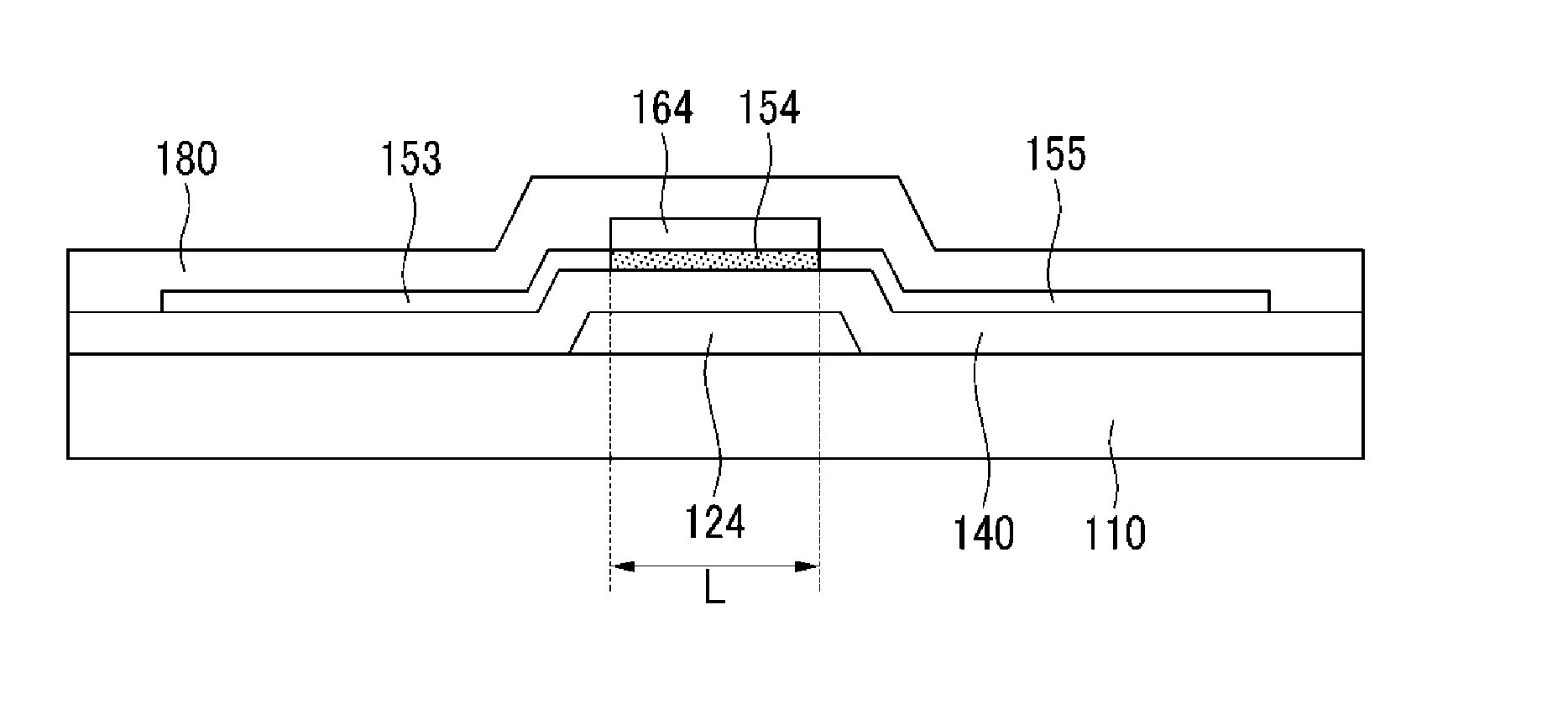
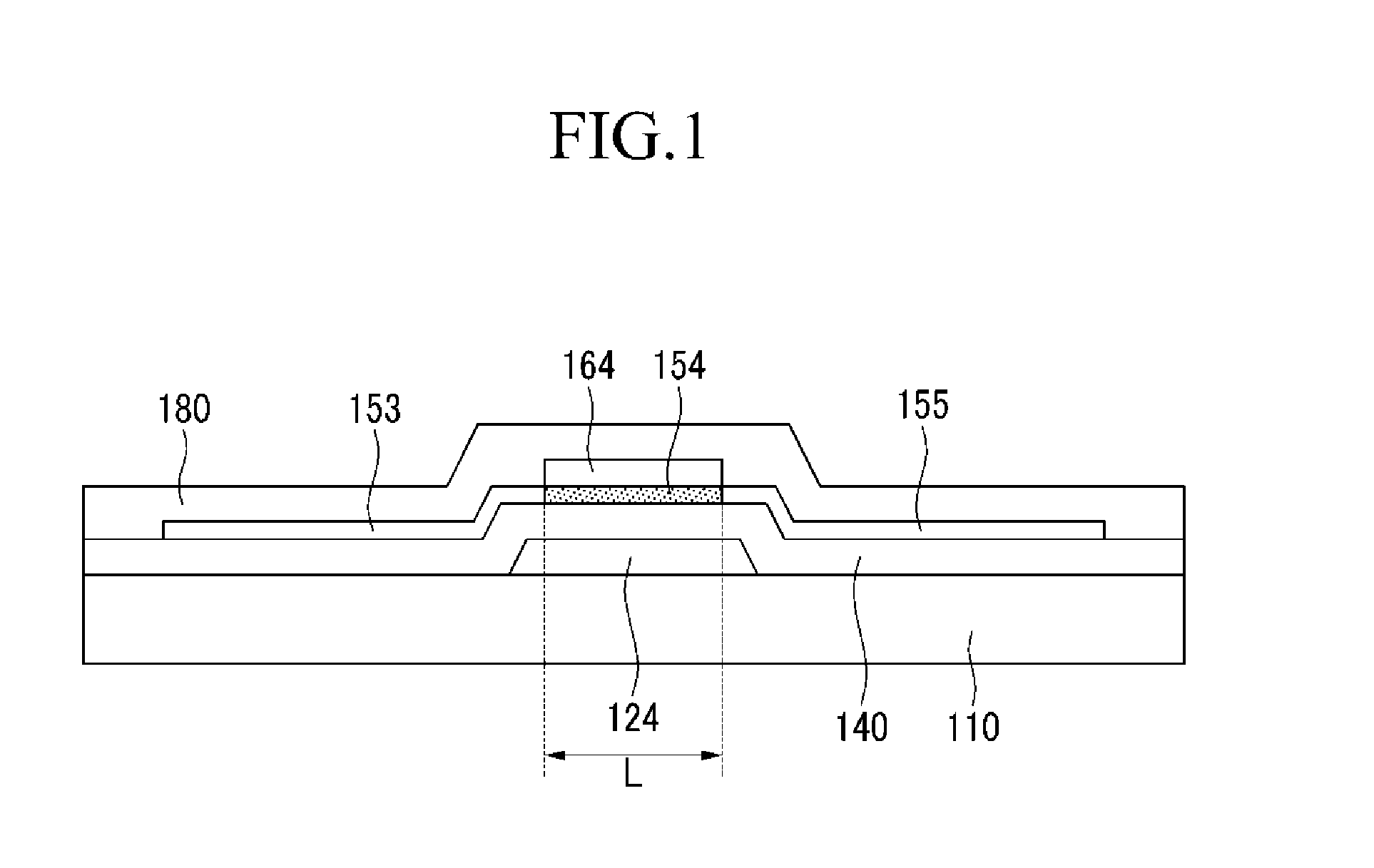
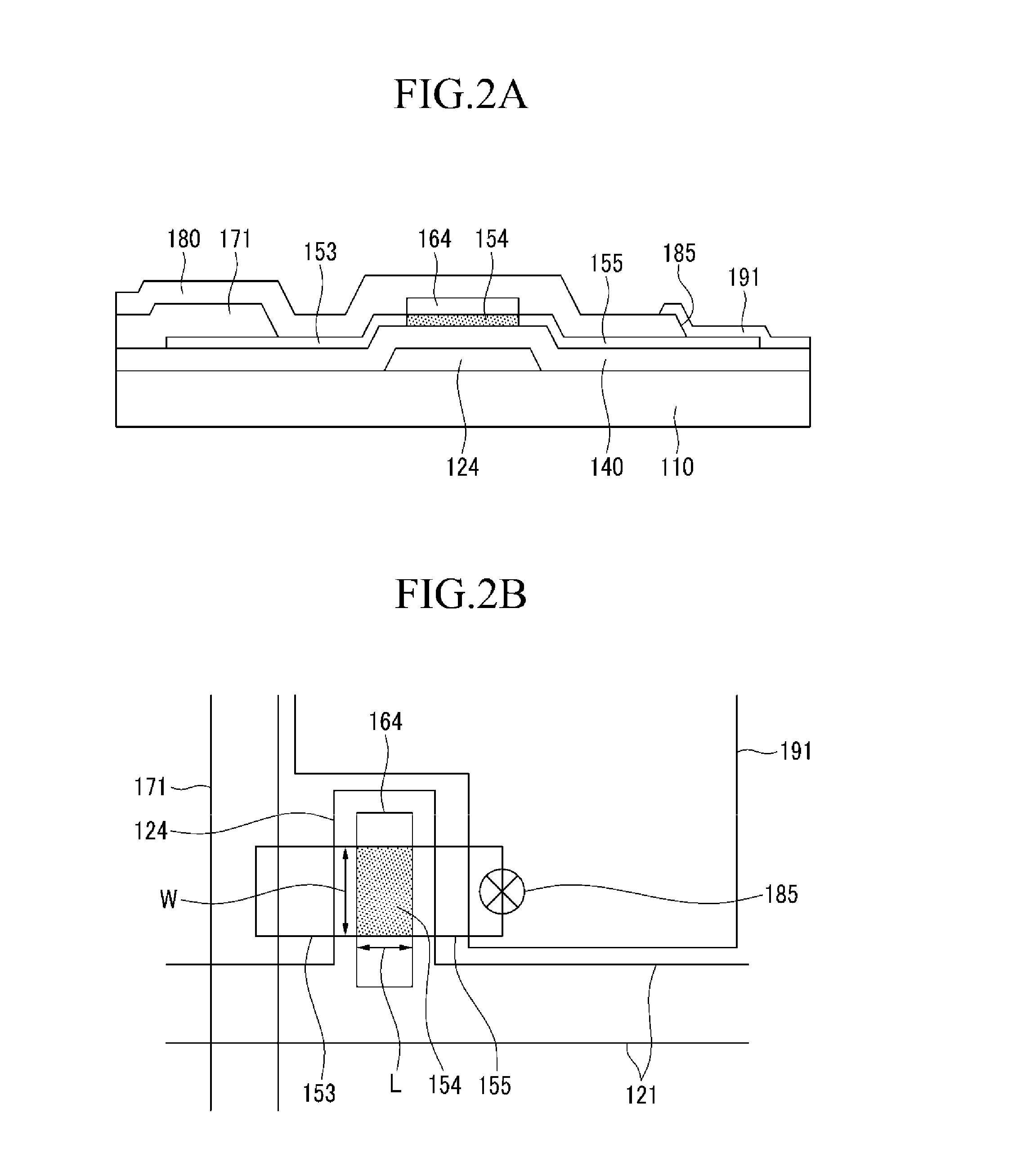
The present invention relates to a thin film transistor, a thin film transistor array panel, and a manufacturing method thereof. A thin film transistor according to an exemplary embodiments of the present invention includes: a gate electrode; a gate insulating layer positioned on or under the gate electrode; a channel region overlapping the gate electrode, the gate insulating layer interposed between the channel region and the gate electrode; and a source region and a drain region, facing each other with respect to the channel region, positioned in the same layer as the channel region, and connected to the channel region, wherein the channel region, the source region, and the drain region comprise an oxide semiconductor, and wherein a carrier concentration of the source region and the drain region is larger than a carrier concentration of the channel region.

Description

CROSS-REFERENCE TO RELATED APPLICATION[0001]This application claims priority to and the benefit of Korean Patent Application No. 10-2012-0059605, filed on Jun. 4, 2012, which is hereby incorporated by reference for all purposes as if fully set forth herein.BACKGROUND OF THE INVENTION[0002]1. Field of the Invention[0003]The present invention relates to a thin film transistor, a thin film transistor array panel, and a manufacturing method thereof.[0004]2. Description of the Related Art[0005]A thin film transistor (TFT) has been used in various electronic devices such as a flat panel display. For example, a thin film transistor has been used as a switching element or a driving element for a flat panel display such as a liquid crystal display (LCD), an organic light emitting diode (OLED) display, and an electrophoretic display.[0006]Typically, a thin film transistor includes a gate electrode connected to a gate line transmitting a scanning signal, a source electrode connected to a data ...

Claims


Application Information

Patent Timeline
Patent Type & Authority Applications(United States)
IPC IPC(8): H01L29/786H01L29/66
CPCH01L29/7869H01L29/66969H01L29/401H01L27/1225H01L29/06H01L29/78618H01L29/78696H01L29/86H01L29/78693H01L29/66742H01L21/28247H01L21/2686H01L21/3086H01L21/02205H01L27/1214H01L29/42356H01L29/0847
Inventor LEE, JE HUNSONG, JUN HOYEO, YUN JONGJUNG, HWA DONG
Owner SAMSUNG DISPLAY CO LTD
Learn More