

Compact, method for producing compact, reactor, converter, and power conversion device
- Summary
- Abstract
- Description
- Claims
- Application Information
AI Technical Summary
Benefits of technology
Problems solved by technology
Method used
Image

Examples
first embodiment
Compact
[0078]A compact according to the present invention is obtained by pressure-forming coated soft magnetic powder that contains a plurality of coated soft magnetic particles each constituted by a soft magnetic particle having an outer periphery coated with an insulating coating and an iron-containing oxide film is present in at least part of a surface of the compact. The feature of the compact is that a particular amount of oxygen is contained in the surface portion where the oxide film is present. In the detailed description below, this feature is mainly described and the structure of the soft magnetic powder is described in the subsequent description of the production method. The constitutional elements of the compact substantially retain the characteristics and properties of ingredients.
[0079]An iron-containing oxide film is present in at least part of a surface of the compact. Assuming that the total content of iron and oxygen in the surface portion of the compact where the ...
second embodiment
Reactor
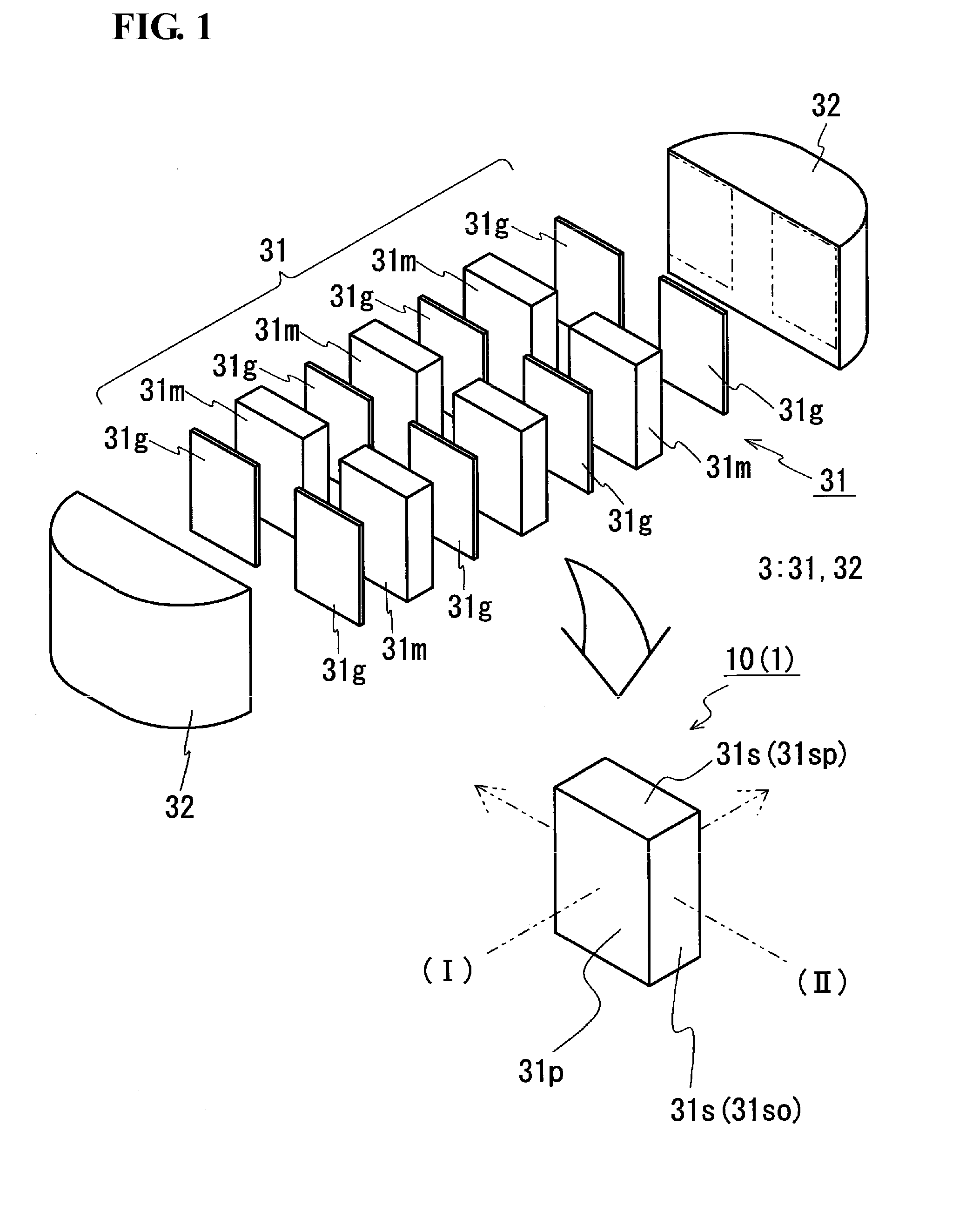
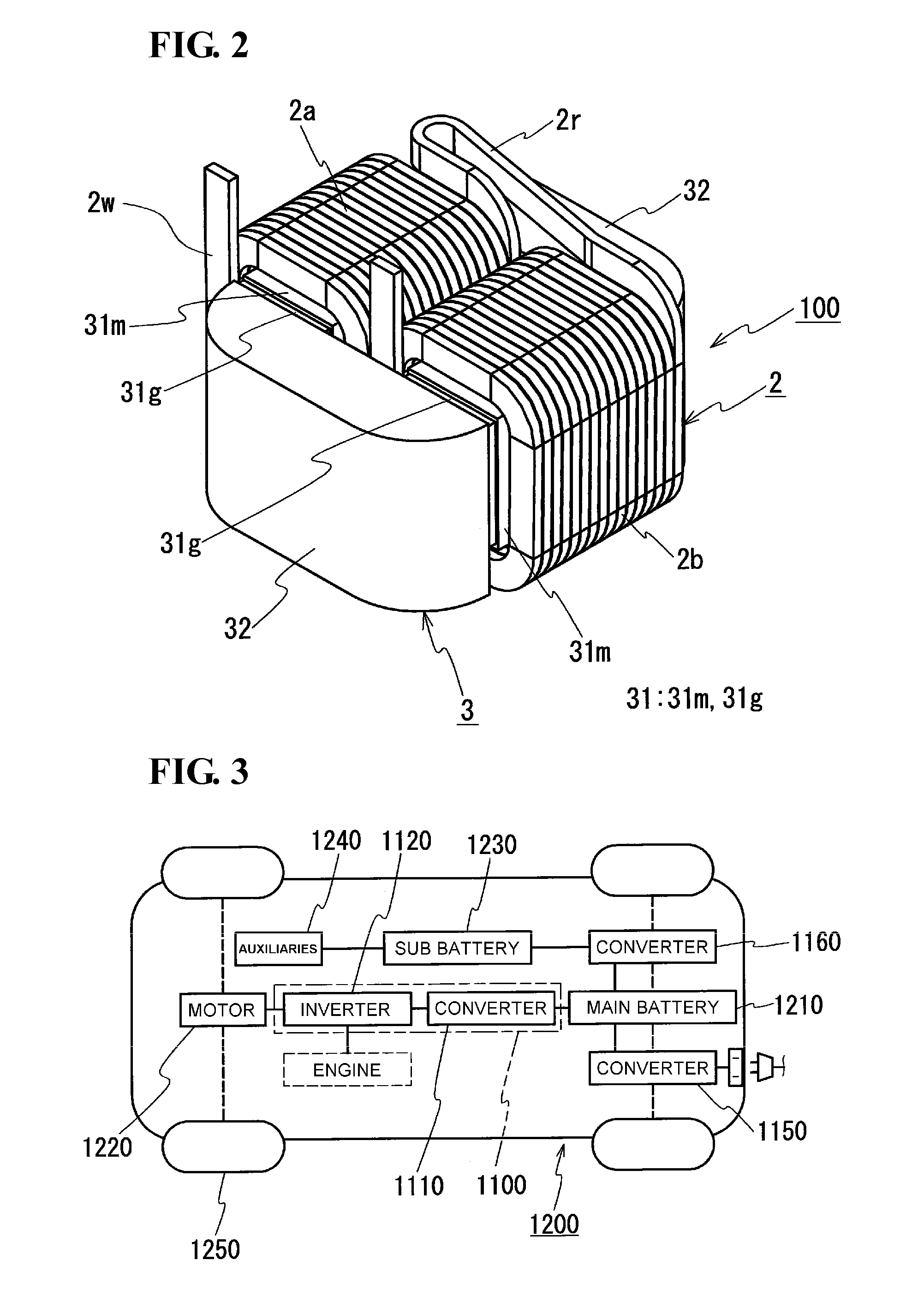
[0153]The compact described above and a compact produced by the above-described method for producing a compact are suitable for use in constitutional members of reactors. For example, a reactor includes a coil obtained by winding a wire, and a magnetic core that is arranged on the inner side and the outer side of the coil and forms a closed magnetic circuit. At least part of the magnetic core is constituted by a compact. This compact may be the compact of the present invention. In other words, the feature of the reactor of the present invention is that the compact described above is used in at least part of the magnetic core of the reactor. An example of the reactor is described below with reference to FIGS. 1 and 2. The description is provided by using an example in which the compacts of the present invention are used in inner core units 31 of a magnetic core 3 of a reactor 100, the inner core units 31 being arranged on the inner side of a coil 2. Known structures of reactor...
third embodiment
Converter and Power Conversion Device
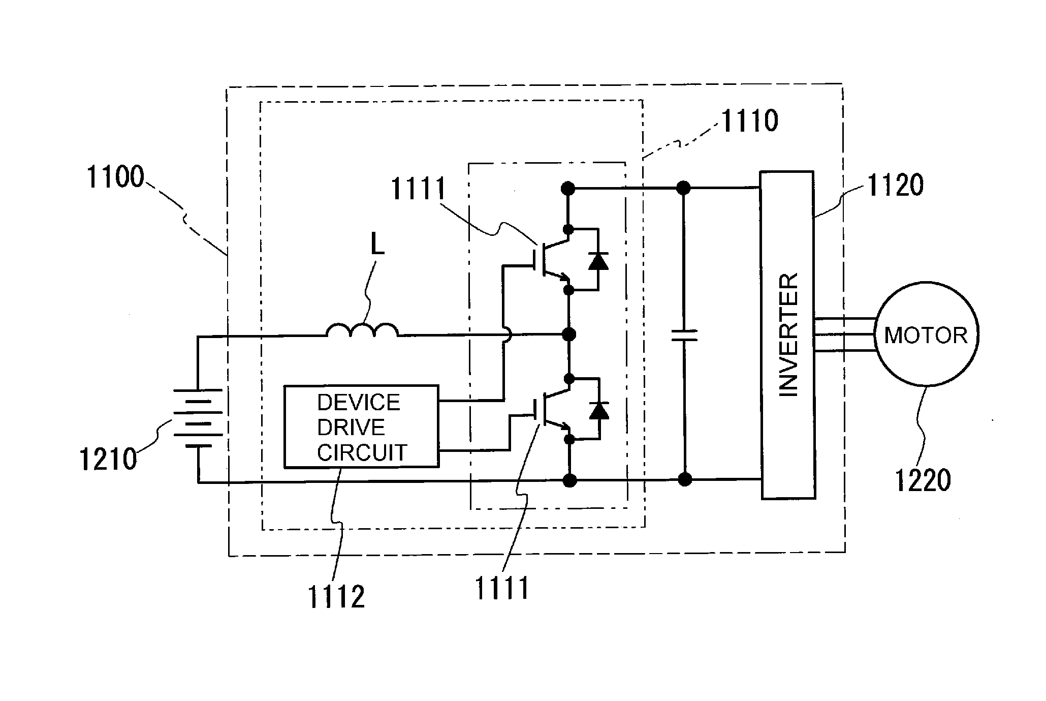
[0164]The reactor described above can be used as a constitutional part of a converter mounted in vehicles, for example, and a constitutional part of a power conversion device that includes the converter.
[0165]For example, as shown in FIG. 3, a vehicle 1200 such as a hybrid car or an electric car includes a main battery 1210, a power conversion device 1100 connected to the main battery 1210, and a motor (load) 1220 driven by power supplied from the main battery 1210 and used for driving. The motor 1220 is typically a three-phase AC motor, drives wheels 1250 during driving, and functions as a power generator during regeneration. When the vehicle 1200 is a hybrid car, an engine is provided in addition to the motor 1220. In FIG. 3, an inlet is illustrated as a portion of the vehicle 1200 at which charging is conducted. Alternatively, the vehicle 1200 may be equipped with a plug.
[0166]The power conversion device 1100 includes a converter 1110 connecte...
PUM
| Property | Measurement | Unit |
|---|---|---|
| Percent by mass | aaaaa | aaaaa |
| Percent by mass | aaaaa | aaaaa |
| Percent by mass | aaaaa | aaaaa |
Abstract
Description
Claims
Application Information