Neurostimulation system with default mri-mode

a neurostimulator and default mode technology, applied in electrotherapy, therapy, etc., can solve the problems of patient tissue damage, neurostimulator malfunction or damage, patient discomfort, etc., and achieve the effect of high impedan

Active Publication Date: 2013-12-05
BOSTON SCI NEUROMODULATION CORP
View PDF4 Cites 11 Cited by
  • Summary
  • Abstract
  • Description
  • Claims
  • Application Information

AI Technical Summary

Benefits of technology

[0017]The method further comprises preventing at least a portion (and preferably all) of the induced electrical current from entering the stimulation output circuitry (e.g., from entering stimulation sources within the stimulation output circuitry) during the EMI protection state. At least a portion of the induced electrical current may be prevented from being conveyed from at least one electrode carried by the stimulation lead(s) and at least another electrode carried by the stimulation lead(s).
[0018]In one method, at least a portion of the induced electrical current is prevented from entering the stimulation output circuitry by applying a high compliance voltage between the at least one electrode carried by the stimulation lead(s) and a ground reference. In another method, at least a portion of the induced electrical current is prevented from entering the stimulation output circuitry by introducing a high impedance between at least one electrode carried by the stimulation lead(s) and the stimulation output circuitry. In still another method, at least a portion of the induced electrical current is prevented from entering the stimulation output circuitry by introducing a low impedance between at least one electrode carried by the stimulation lead(s) and a ground reference. In yet another method, at least a portion of the induced electrical current is prevented from entering the stimulation output circuitry by preventing power from being supplied by a power supply to the stimulation output circuitry.

Problems solved by technology

Thus, when designing implantable neurostimulation systems, consideration must be given to the possibility that the patient in which a neurostimulator is implanted may be subjected to electro-magnetic energy from MRI scanners, which may potentially cause damage to patient tissue, malfunction or damage or the neurostimulator, and / or discomfort to the patient.
Because the stimulation leads can act as antennas that collect RF energy, the strength of the RF field generated by a conventional MRI scanner may be high enough to induce voltages on to the stimulation lead(s), which in turn, are seen by the IPG electronics, where it can affect the behavior of the IPG and even result in permanent damage.
Even if the total RF energy induced on the stimulation leads could be tolerated by the IPG, undesirable high energy pulses or resulting hot spots may impact IPG performance.
The strength of the gradient magnetic field generated by a conventional MRI scanner can also induce voltage on the stimulation leads, which if higher than the voltage supply rails of the IPG electronics, could cause unwanted stimulation to the patient due to the similar frequency band, between the MRI-generated gradient field and intended stimulation energy frequencies for therapy, as well as potentially damaging the electronics within the IPG.
For example, in a conventional neurostimulation system, an induced voltage at the connector of the IPG that is higher than IPG battery voltage (typically ˜3-5V), may induce such unwanted stimulation currents.
Therefore, there is a chance that the IPG may not be in the appropriate mode if the IPG resets, if the IPG experiences a failure, if there is failure to detect the occurrence of an MRI, or if there is failure to instruct the IPG to be placed in the MRI mode.

Method used


Image

  • Neurostimulation system with default mri-mode
  • Neurostimulation system with default mri-mode
  • Neurostimulation system with default mri-mode

Examples


Embodiment Construction

[0030]The description that follows relates to a spinal cord stimulation (SCS) system. However, it is to be understood that while the invention lends itself well to applications in SCS, the invention, in its broadest aspects, may not be so limited. Rather, the invention may be used with any type of implantable electrical circuitry used to stimulate tissue. For example, the present invention may be used as part of a multi-lead system such as a pacemaker, a defibrillator, a cochlear stimulator, a retinal stimulator, a stimulator configured to produce coordinated limb movement, a cortical stimulator, a deep brain stimulator, peripheral nerve stimulator, microstimulator, or in any other neural stimulator configured to treat urinary incontinence, sleep apnea, shoulder sublaxation, headache, etc.

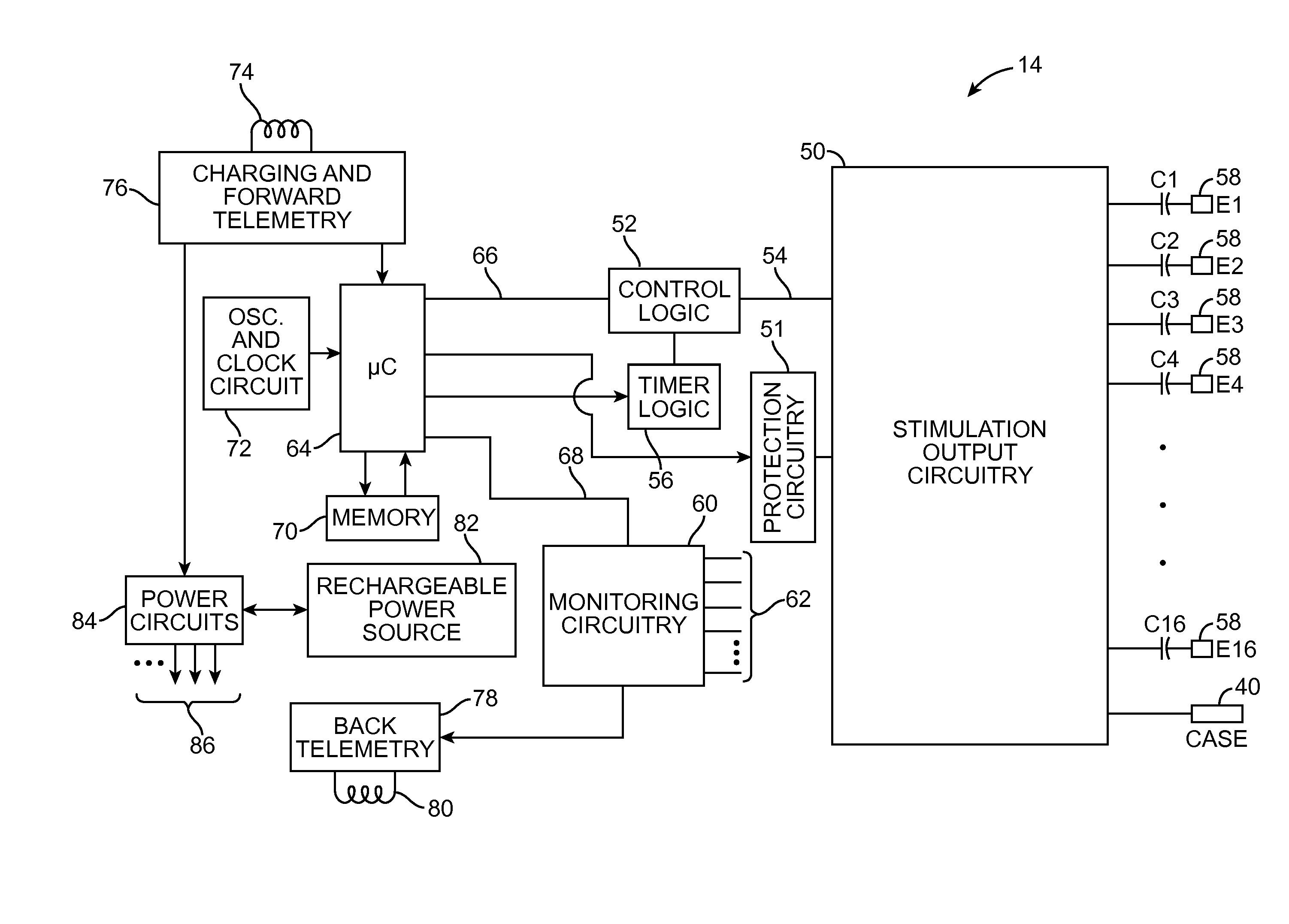
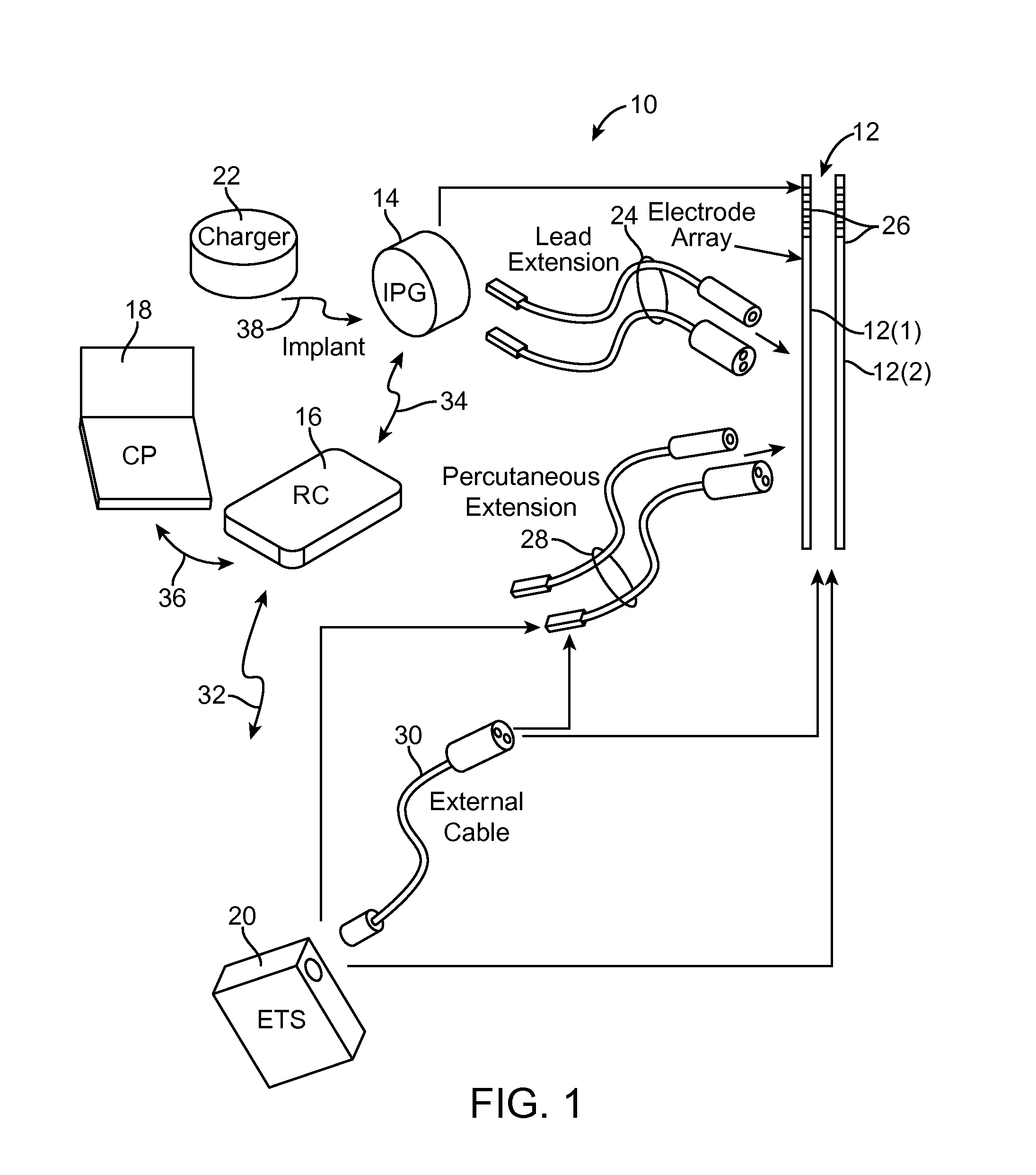
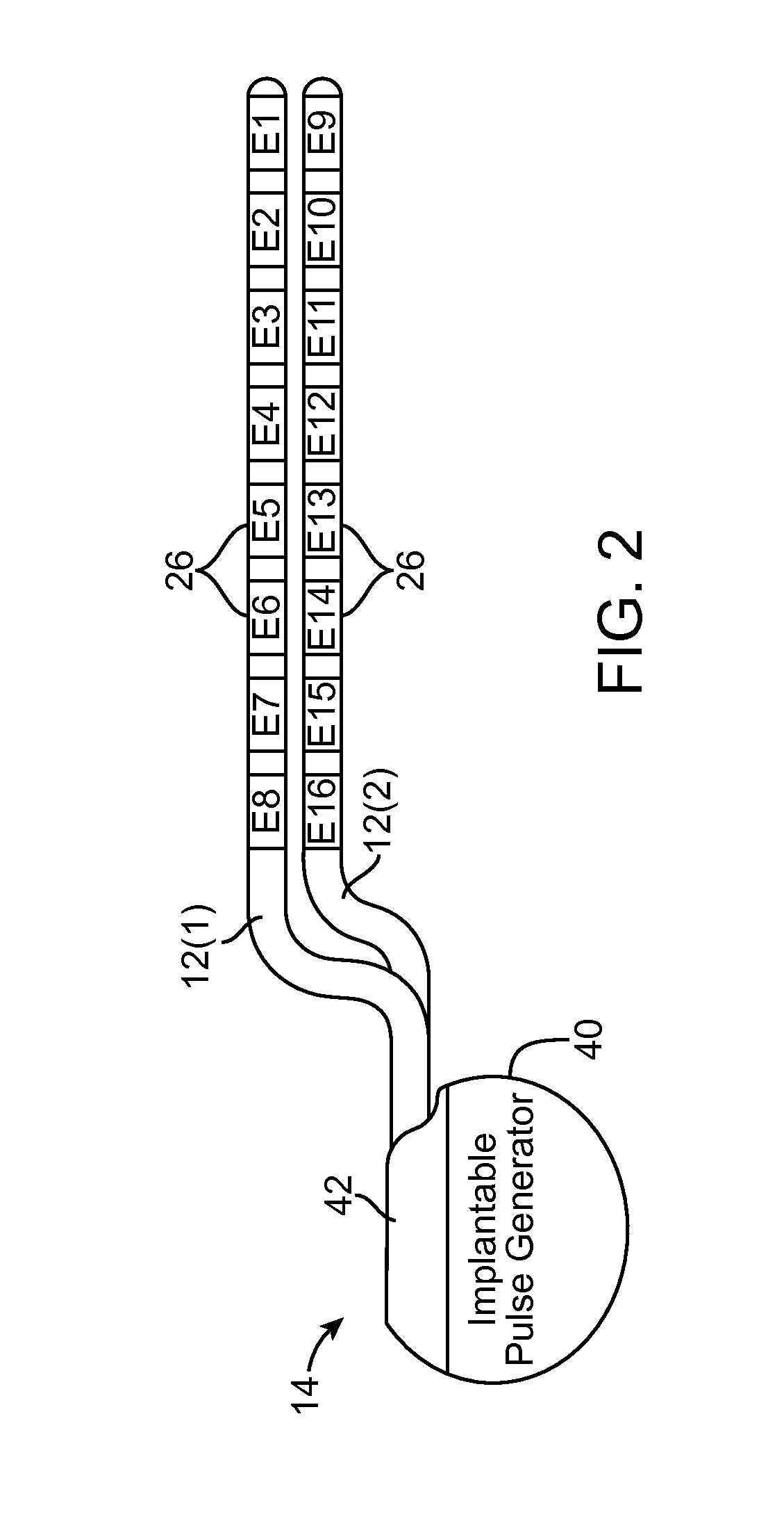
[0031]Turning first to FIG. 1, an exemplary SCS system 10 generally comprises a plurality of percutaneous stimulation leads 12 (in this case, two percutaneous leads 12(1) and 12(2)), an implantable...


PUM


Abstract

A neurostimulation device capable of being placed between a stimulation state and an EMI protection state. The neurostimulation device comprises a plurality of electrical terminals configured for being respectively coupled to a plurality of stimulation electrodes, stimulation output circuitry configured for being selectively activated during the stimulation state to output a plurality of stimulation pulses to the plurality of electrical terminals, electromagnetic protection circuitry configured for being selectively activated during the EMI protection state to prevent at least a portion of the electrical current induced on at least one of the electrical terminals by an electromagnetic field entering the stimulation output circuitry, and a controller configured for automatically defaulting the neurostimulation device to the EMI protection state.

Description

RELATED APPLICATION DATA[0001]The present application claims the benefit under 35 U.S.C. §119 to U.S. provisional patent application Ser. No. 61 / 655,938, filed Jun. 5, 2012. The foregoing application is hereby incorporated by reference into the present application in its entirety.FIELD OF THE INVENTION[0002]The present invention relates to implantable tissue stimulation systems for use in a magnetic resonance imaging (MRI) environment.BACKGROUND OF THE INVENTION[0003]Implantable neurostimulation systems have proven therapeutic in a wide variety of diseases and disorders. Pacemakers and Implantable Cardiac Defibrillators (ICDs) have proven highly effective in the treatment of a number of cardiac conditions (e.g., arrhythmias). Spinal Cord Stimulation (SCS) systems have long been accepted as a therapeutic modality for the treatment of chronic pain syndromes, and the application of tissue stimulation has begun to expand to additional applications such as angina pectoralis and incontine...

Claims


Application Information

Patent Timeline
Patent Type & Authority Applications(United States)
IPC IPC(8): A61N1/372
CPCA61N1/37211A61N1/08A61N1/3718A61N1/086
Inventor CARBUNARU, RAFAELMURTONEN, SALOMOPARRAMON, JORDIVENOOK, ROSS
Owner BOSTON SCI NEUROMODULATION CORP
Why Eureka
Try Eureka