This helps you quickly interpret patents by identifying the three key elements:
Problems solved by technology
Method used
Benefits of technology
[0029]Another embodiment provides a method for cooling a cavity in a portable electronic device. During operation of the portable electronic device, the forced-fluid driver generates the fluid flows through the fluid-flow port so that thermal power associated with operation of at least an integrated circuit in the cavity is transported out of the cavity, where the fluid flows include the central fluid flow sandwiched between two additional fluid flows, and the central fluid flow has the higher temperature than those of the additional fluid flows. Moreover, the housing directs the central fluid flow away from the rotatable disp
Problems solved by technology
However, heat-dissipation mechanisms for portable electronic devices generally involve the use of additional parts and/or materials.
Such heat-dissipating parts and/or materials may take up space within the portable electronic devices and may add to the cost of the portable electronic devices.
In addition, the heat-dissipating parts and/or materials result in exhaust
Method used
Image
Click on the blue label to locate the original text in one second.
Reading with bidirectional positioning of images and text.
Examples
Example
[0055]Note that like reference numerals refer to corresponding parts throughout the drawings. Moreover, multiple instances of the same part are designated by a common prefix separated from an instance number by a dash.
DETAILED DESCRIPTION
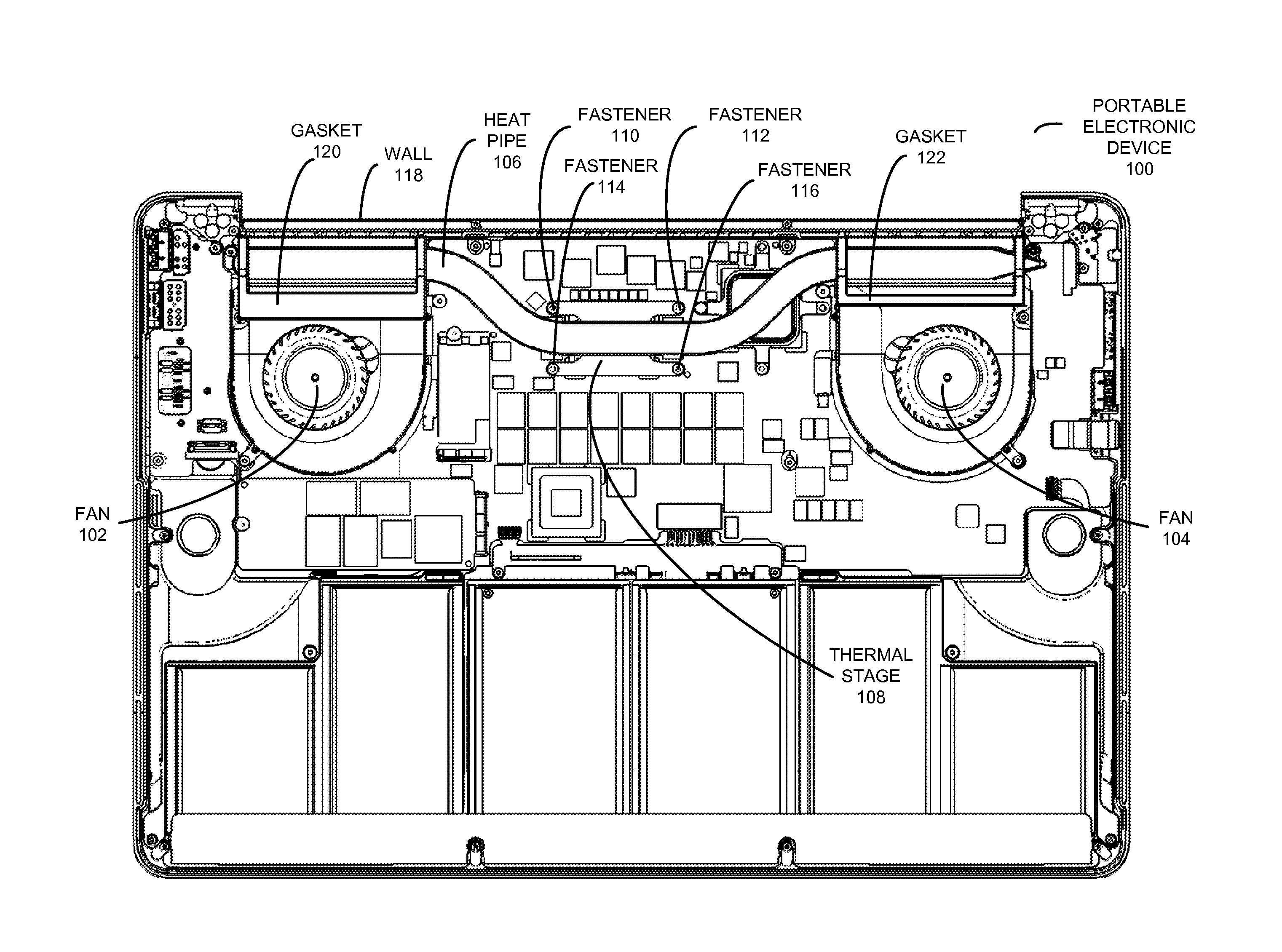
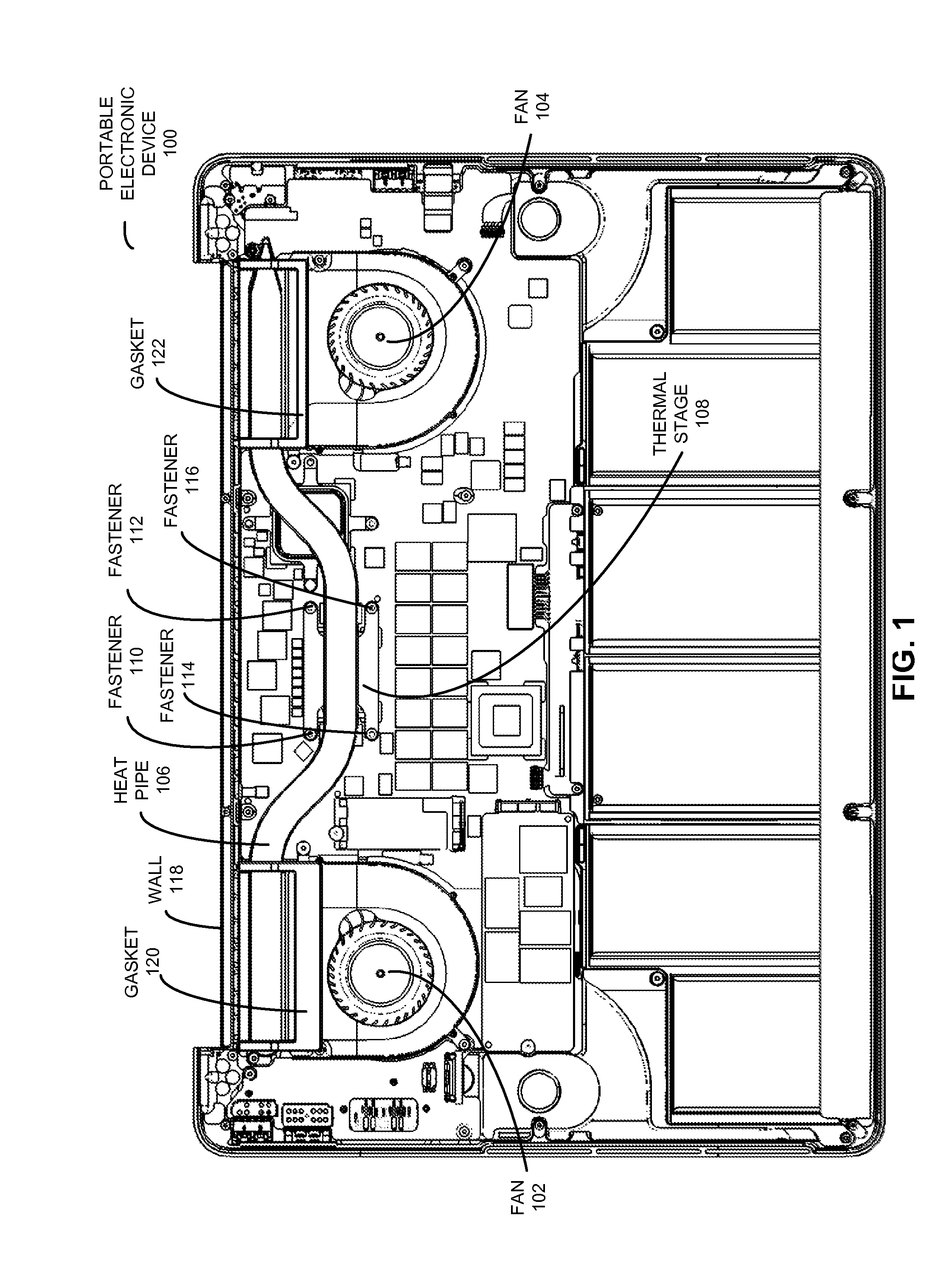
[0056]FIG. 1 shows a bottom view of a portable electronic device 100, such as a laptop computer, with the bottom of the enclosure of portable electronic device 100 removed. Within portable electronic device 100, a number of components may be used to cool heat-generating components such as central-processing units (CPUs), graphics-processing units (GPUs), and / or video memory.
[0057]First, portable electronic device 100 may include a set of fans 102-104 for expelling heat generated by the heat-generating components outside portable electronic device 100. Fans 102-104 may utilize a set of intake and exhaust vents along a wall 118 of portable electronic device 100 to draw in cooler air from outside portable electronic device 100, circulate the air around...
PUM
Property
Measurement
Unit
Angle
aaaaa
aaaaa
Angle
aaaaa
aaaaa
Angle
aaaaa
aaaaa
Abstract
The disclosed embodiments related to a component for use in a portable electronic device. The component includes a wall of the portable electronic device, containing an intake zone that includes a set of intake vents directed at a first angle toward one or more heat-generating components of the portable electronic device. The wall also includes an exhaust zone containing a set of exhaust vents directed at a second angle out of the portable electronic device.
Description
CROSS REFERENCE TO RELATED APPLICATION[0001]This application claims priority under 35 U.S.C. §119(e) to: U.S. Provisional Application Ser. No. 61 / 657,505, entitled “Optimized Vent Walls in Electronic Devices,” by Brett W. Degner, Bartley K. Andre, Jeremy D. Bataillou, Jay S. Nigen, Christiaan A. Ligtenberg, Ron A. Hopkinson, Charles A. Schwalbach, Matthew P. Casebolt, Nicholas A. Rundle and Frank F. Liang, Attorney docket number APL-P14985USP1, filed on Jun. 8, 2012; U.S. Provisional Application Ser. No. 61 / 657,500, entitled “Heat Exchanger with Dual Bypass,” by Jay S. Nigen and Brett W. Degner, Attorney docket number APL-P15189USP1, filed on Jun. 8, 2012; and U.S. Provisional Application Ser. No. 61 / 657,492, entitled “Fluid-Flow Bifurcation Using Clutch Barrel,” by Brett W. Degner, Jay S. Nigen, Bartley K. Andre, and Jeremy D. Bataillou, Attorney docket number APL-P15190USP1, filed on Jun. 8, 2012, the contents of each of which are herein incorporated by reference.BACKGROUND[0002]1...
Claims
Application Information
Patent Timeline
Application Date:The date an application was filed.
Publication Date:The date a patent or application was officially published.
First Publication Date:The earliest publication date of a patent with the same application number.
Issue Date:Publication date of the patent grant document.
PCT Entry Date:The Entry date of PCT National Phase.
Estimated Expiry Date:The statutory expiry date of a patent right according to the Patent Law, and it is the longest term of protection that the patent right can achieve without the termination of the patent right due to other reasons(Term extension factor has been taken into account ).
Invalid Date:Actual expiry date is based on effective date or publication date of legal transaction data of invalid patent.
IPC IPC(8): H05K7/20H05K13/00B29C47/88G06F1/20
CPCG06F1/203Y10T29/49002H05K7/20145H05K7/2039
Inventor DEGNER, BRETT W.ANDRE, BARTLEY K.BATAILLOU, JEREMY D.NIGEN, JAY S.LIGTENBERG, CHRISTIAAN A.HOPKINSON, RON A.SCHWALBACH, CHARLES A.CASEBOLT, MATTHEW P.RUNDLE, NICHOLAS A.LIANG, FRANK F.