Magnetic-separation filter device

a filter device and magnetic separation technology, applied in the direction of filtering separation, separation process, moving filter element filter, etc., can solve the problems of reducing machine drive reliability, machinability and cleaning efficiency, etc., to reduce magnetic loss, high magnetic permeability, and high permeability

Active Publication Date: 2013-12-12
NIPPON STEEL & SUMIKIN ENG CO LTD
View PDF2 Cites 7 Cited by
  • Summary
  • Abstract
  • Description
  • Claims
  • Application Information

AI Technical Summary

Benefits of technology

[0018]In the magnetic-separation filter device according to the present invention, the first region defined by the substantially cylindrical housing and the partition plate is filled with the filter medium formed of fine amorphous-alloy wire bundle and the permanent magnet is disposed as a magnetizer at a position outside the housing opposed to the first region to foam a magnetic field in the first region.
[0019]Accordingly, since pressure resistance can be guaranteed by the cylindrical housing, the magnetic-separation filter device can be applied to a high-pressure fluid as well as a normal-pressure fluid. Since a magnetic path is formed in the first region defined by the parallel partition plate, a magnetic flux of the opposed permanent magnet is not spread to the outside from the first region and a high-level parallel magnetic field without leakage of a magnetic field is uniformly formed, contaminants of fine ferromagnetic particles included in the fluid can be adsorbed on the fine amorphous-alloy wire bundle.
[0020]Since the permanent magnet is connected to the yoke formed of a material having high magnetic permeability as the magnetizer, it is possible to construct a closed magnetic path without loss and the first region and thus to uniformly form a high-level magnetic field in the first region.
[0021]Since the teeth formed of a material having no residual magnetism with high permeability are filled in the gap between the permanent magnet and the first region of the housing and the contact surface of the teeth and the permanent magnet is planar, the teeth and the permanent magnet come in close contact with each other at the contact surface to reduce magnetic loss and to eventually ensure easy attachment and detachment of the magnetizer including the permanent magnet.
[0022]Since the magnetic-separation filter device includes the on-off driver that causes the magnetizer to be configured with the permanent magnet and the yoke, in close contact with the first region of the housing and to be separable from the housing, the magnetic field in the first region disappears and the magnetic field gradient of the fine amorphous-alloy wire bundle disappears to remove the adsorptive force of fine ferromagnetic particles and to perform other operations such as backwashing, by separating the magnetizer from the housing to a separately-evacuated position to turn off the magnetization. At this time, since the residual magnetic flux density of the fine amorphous-alloy wire bundle is low, the adsorptive force is close to zero and thus the backwashing can be easily performed. Thereafter, by arranging the magnetizer in close contact with the first region of the housing to turn on the magnetization, a magnetic field is formed in the first region to generate an adsorptive force of fine ferromagnetic particles by the magnetic field gradient of the fine amorphous-alloy wire bundle. Thereby the contaminants of fine ferromagnetic particles are captured and adsorbed.
[0023]The on-off control between close contact arrangement and separated arrangement of the magnetizer in relation to the permanent magnet and the york is determined on the basis of one or more pieces of data on a magnetization time by a timer, a differential pressure between upstream and downstream of the filter medium, and an integrated flow volume of a fluid passing through the filter medium. Accordingly, it is possible to adsorb contaminants in the fluid and it is possible to stop the operation of adsorbing contaminants at an appropriate time and to perform other operations such as backwashing, while appropriately retarding clogging of the magnetic-separation filter at the time of the magnetization on-off control between the closely-opposed arrangement and the separately-evacuated arrangement of the magnetizer by the on-off driver. As a result, it is possible to prevent clogging trouble and to extend the maintenance intervals.

Problems solved by technology

The oils or liquids including the contaminants cause problems such as a decrease in machine drive reliability and a decrease in machinability and cleaning efficiency.

Method used


Image

  • Magnetic-separation filter device
  • Magnetic-separation filter device
  • Magnetic-separation filter device

Examples


Embodiment Construction

, and a comparative example depending on presence or absence of a partition plate in the housing, where FIG. 11(a) illustrates a magnetic flux density in the radius direction and FIG. 11(b) illustrates a magnetic flux density in the length direction.

[0041]FIG. 12 is a diagram illustrating a variation in magnetic flux density in the housing in Example 1, Example 2, and the comparative example.

MODE FOR CARRYING OUT THE INVENTION

[0042]Hereinafter, a magnetic-separation filter device according to an embodiment of the present invention will be described with reference to the accompanying drawings.

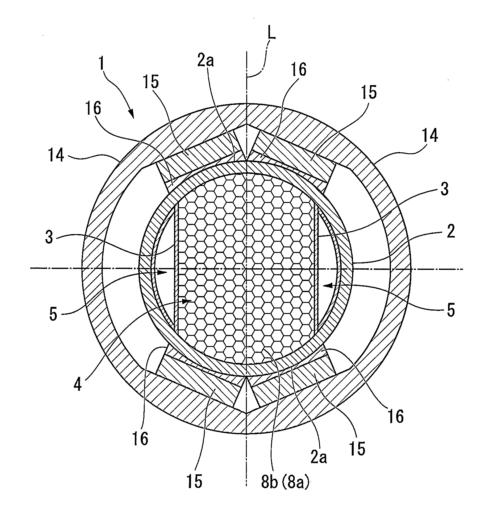
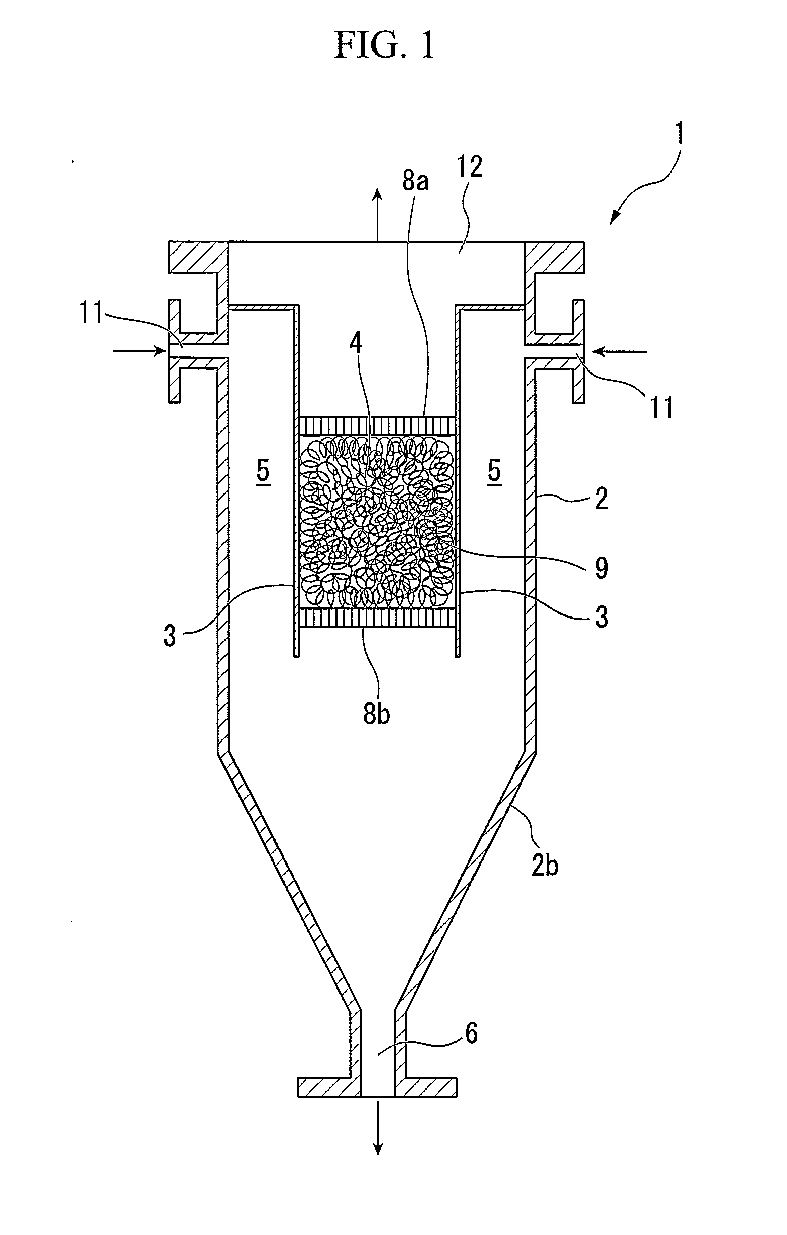
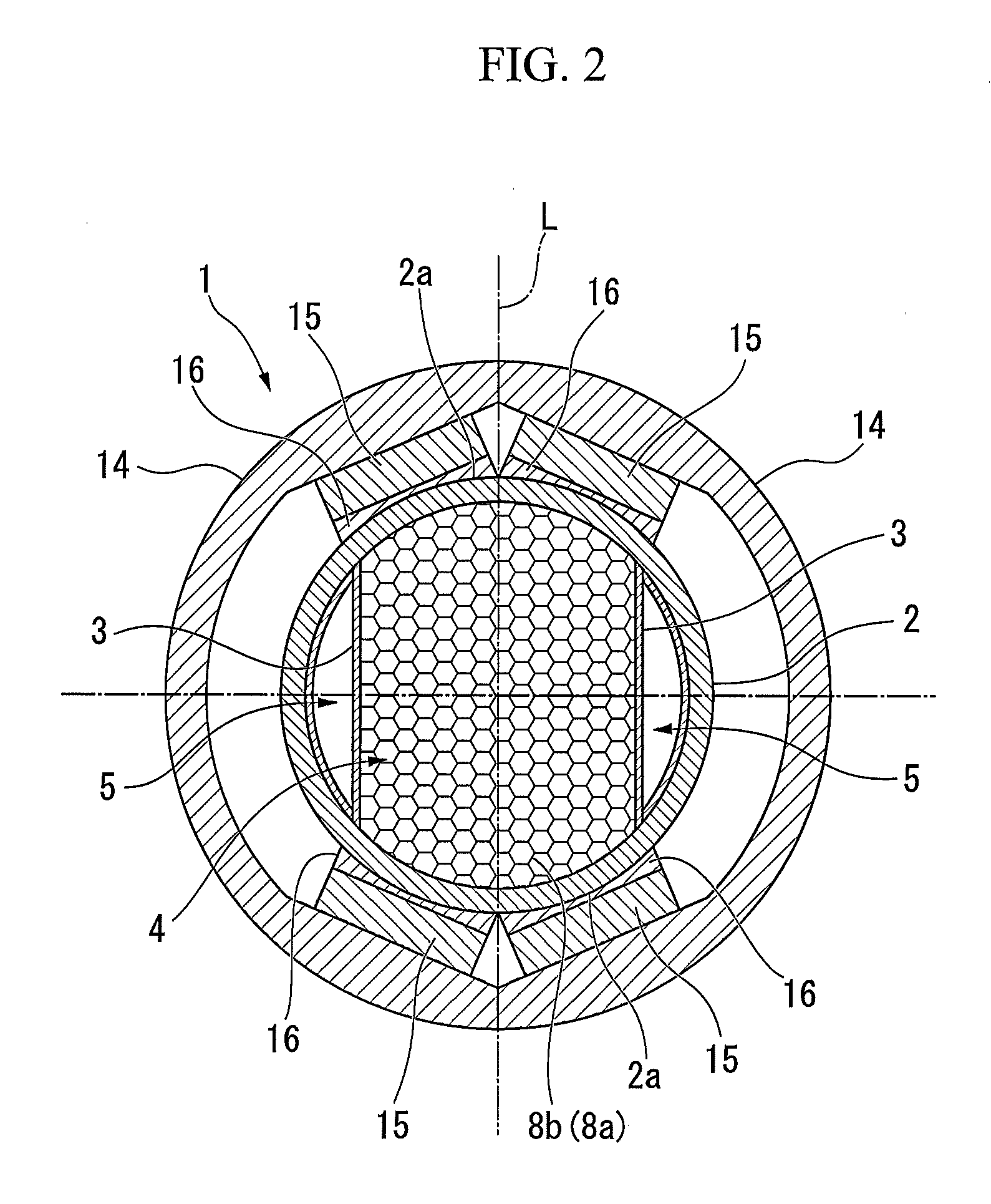
[0043]In a magnetic-separation filter device 1 shown in FIGS. 1 and 2, a partition plate 3 formed of nonmagnetic metal and including a pair of substantially parallel plates extends downward in a substantially cylindrical housing 2 arranged in the vertical direction. The lower end of the partition plate 3 has a length equal to or less than the lower end of the trunk of the housing 2. The upper en...


PUM

PropertyMeasurementUnit
linear velocityaaaaaaaaaa
magnetic fieldaaaaaaaaaa

Abstract

According to an aspect of the present invention, there is provided a magnetic-separation filter device that removes contaminants of fine ferromagnetic particles from a fluid containing such contaminants, comprising: a substantially cylindrical housing; two partition plates that are disposed in an inside of the housing so as to extend in a vertical direction of the housing, dividing the inside of the housing by being disposed in parallel to each other;
a filter medium that includes a fine amorphous-alloy wire bundle filled in a first region defined by the housing and the two partition plates; and
plural permanent magnets that are provided on both sides of the first region outside the housing, wherein the contaminants of fine ferromagnetic particles are adsorbed on the filter media by flowing the fluid containing such contaminants through the first region in which the magnetic field has been formed by these plural permanent magnets.

Description

TECHNICAL FIELD[0001]The present invention relates to a magnetic-separation filter device that can remove ferromagnetic inflow contaminants from a process fluid even under a high pressure and a high temperature in a process plant or the like.[0002]Priority is claimed on Japanese Patent Application No. 2011-041654, filed Feb. 28, 2011, the content of which is incorporated herein by reference.BACKGROUND ART[0003]Iron powder and the like generated with machining or internal abrasion are suspended as contaminants of fine ferromagnetic particles in oils or liquids such as machine lubricant or machining oil. The oils or liquids including the contaminants cause problems such as a decrease in machine drive reliability and a decrease in machinability and cleaning efficiency. Accordingly, a filter device has been proposed which can remove contaminants of fine ferromagnetic particles from the oils or liquids. For example, a magnetic-separation oil purifier described in PTL 1 includes a filter ...

Claims


Application Information

Patent Timeline
Patent Type & Authority Applications(United States)
IPC IPC(8): B03C1/034
CPCB03C1/034B03C1/0332B03C1/288B03C2201/18
Inventor MURAHASHI, KAZUKIMORITA, KENTAROUKATO, YUZURUMURATA, ATSUSHI
Owner NIPPON STEEL & SUMIKIN ENG CO LTD
Why Eureka
Try Eureka