
Application of electrochemical impedance spectroscopy in sensor systems, devices, and related methods

Active Publication Date: 2013-12-12
MEDTRONIC MIMIMED INC
View PDF6 Cites 64 Cited by
  • Summary
  • Abstract
  • Description
  • Claims
  • Application Information

AI Technical Summary

Benefits of technology

The patent describes a method for performing real-time sensor diagnostics and detecting interferents in a subcutaneous or implanted sensor. The method involves performing electrochemical impedance spectroscopy (EIS) procedures to obtain impedance-related data for the sensor's electrodes. This data is then used to determine if the sensor is functioning normally, or if there is an interferent in close proximity to the electrodes. The method can also be used to calibrate the sensor during a period of sensor transition. The technical effects of this patent include improved sensor diagnostics and detection of interferents, as well as improved sensor calibration.

Problems solved by technology

This is an inconvenience for the patient and in some cases may cause the patient not to utilize a continuous glucose measurement system.
Further, when a glucose sensor is first inserted into a patient's skin or subcutaneous layer, the glucose sensor does not operate in a stable state.
In the past, sensor stabilization used to take several hours.
Thus, even with this procedure, sensor stabilization still requires a large amount of time.
If the electrodes of the sensor are not sufficiently hydrated, the result may be inaccurate readings of the patient's physiological condition.
If they are utilized too early, current blood glucose sensors do not operate in an optimal or efficient fashion.
No automatic procedure or measuring technique is utilized to determine when to power on the sensor.
This manual process is inconvenient and places too much responsibility on the patient, who may forget to apply or turn on the power source.
Besides the stabilization and wetting problems during the initial stages of sensor life, there can be additional issues during the sensor's life.
Although sensors may continue to function and deliver a signal after the pre-set operating life of the sensor, the sensor readings eventually become less consistent and thus less reliable after the pre-set operating life of the sensor has passed.
Although the continuous glucose measurement system can monitor the length of time since the sensor was inserted and indicate the end of the operating life of a sensor to warn the user to replace the sensor, it does not have enough safeguards to prevent the sensor from being used beyond the operating life.
Thus, there is a loophole in the system where a user can keep the sensors active longer than recommended and thus compromise the accuracy of the blood glucose values returned by the glucose monitor.
Moreover, the sensor often absorbs polluting species, such as peptides and small protein molecules during the life of the sensor.
Such polluting species can reduce the electrode surface area or diffusion pathway of analytes and / or reaction byproducts, thus reducing the sensor accuracy.
Determining when such pollutants are affecting the sensor signal and how to remedy such conditions is quite significant in sensor operation.
The current state of the art in continuous glucose monitoring (CGM) is largely adjunctive, meaning that the readings provided by a CGM device (including, e.g., an implantable or subcutaneous sensor) cannot be used without a reference value in order to make a clinical decision.
The reference value is needed because there is a limited amount of information that is available from the sensor / sensing component.
However, given the number and level of complexity of the multitude of sensor failure modes, no satisfactory solution has been found.
As such, by itself, the Isig is not a reliable source of information for sensor diagnostics, nor is it a reliable predictor for continued sensor performance.
Another limitation that has existed in the art thus far has been the lack of sensor electronics that can not only run the sensor, but also perform real-time sensor and electrode diagnostics, and do so for redundant electrodes, all while managing the sensor's power supply.
However, up until now, there has been little to no success in using electrode redundancy not only for obtaining more than one reading at a time, but also for assessing the relative health of the redundant electrodes, the overall reliability of the sensor, and the frequency of the need, if at all, for calibration reference values.
In addition, even when redundant sensing electrodes have been used, the number has typically been limited to two.
Again, this has been due partially to the absence of advanced electronics that run, assess, and manage a multiplicity of independent working electrodes (e.g., up to 5 or more) in real time.
Another reason, however, has been the limited view that redundant electrodes are used in order to obtain “independent” sensor signals and, for that purpose, two redundant electrodes are sufficient.
However, heretofore, no glucose-independent means for performing such detection and assessment have been found.

Method used


Image

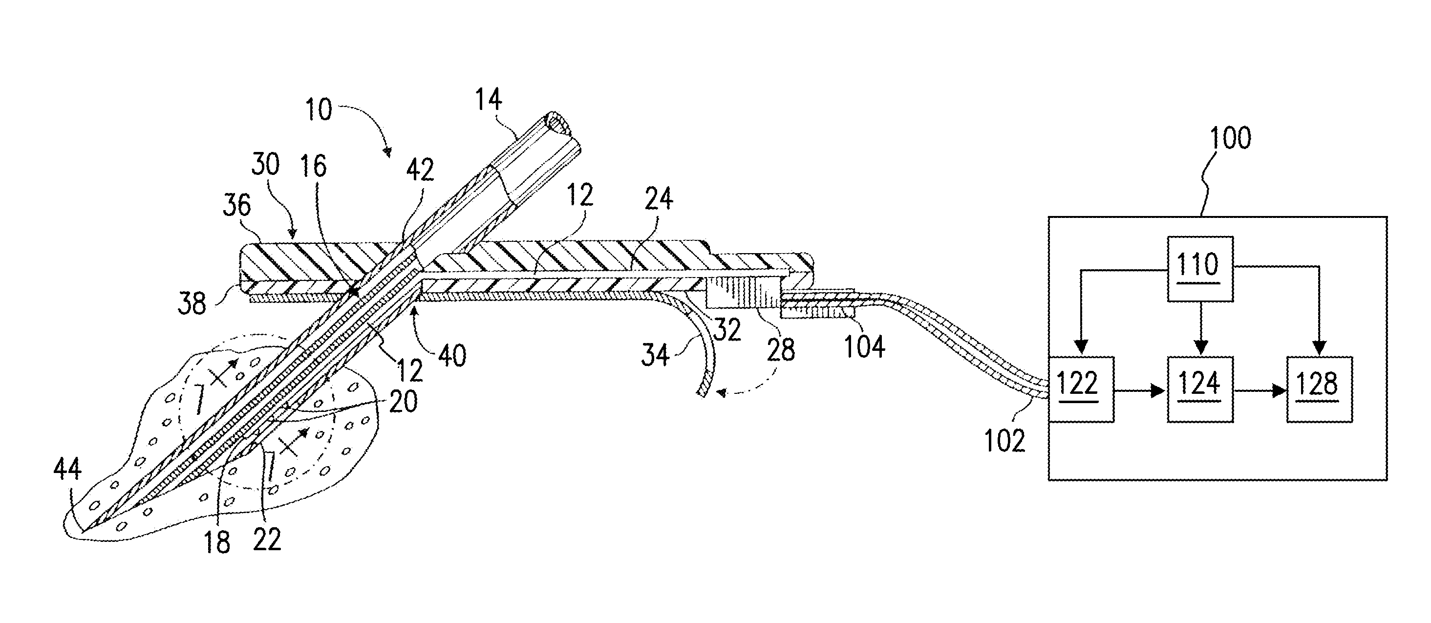
  • Application of electrochemical impedance spectroscopy in sensor systems, devices, and related methods
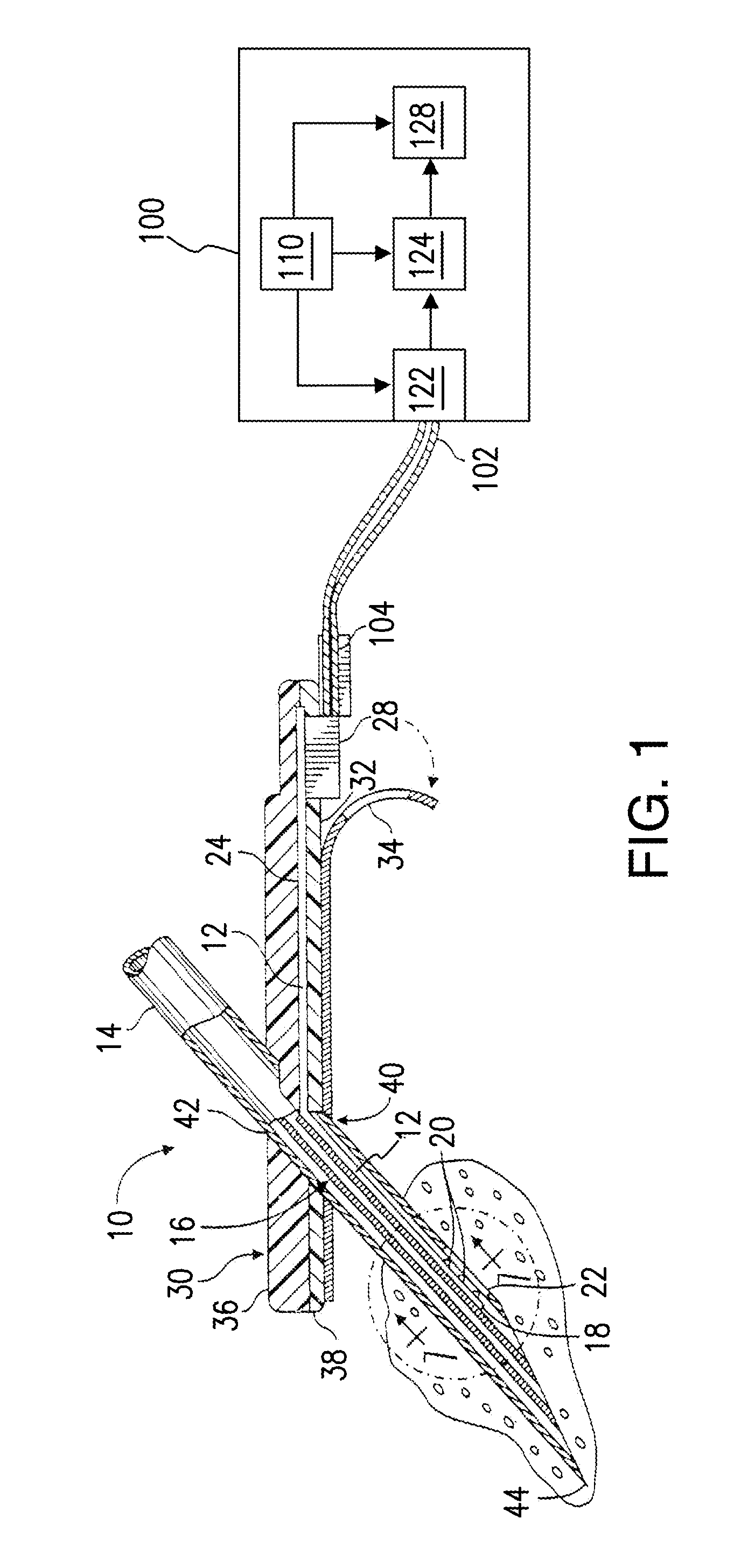
  • Application of electrochemical impedance spectroscopy in sensor systems, devices, and related methods
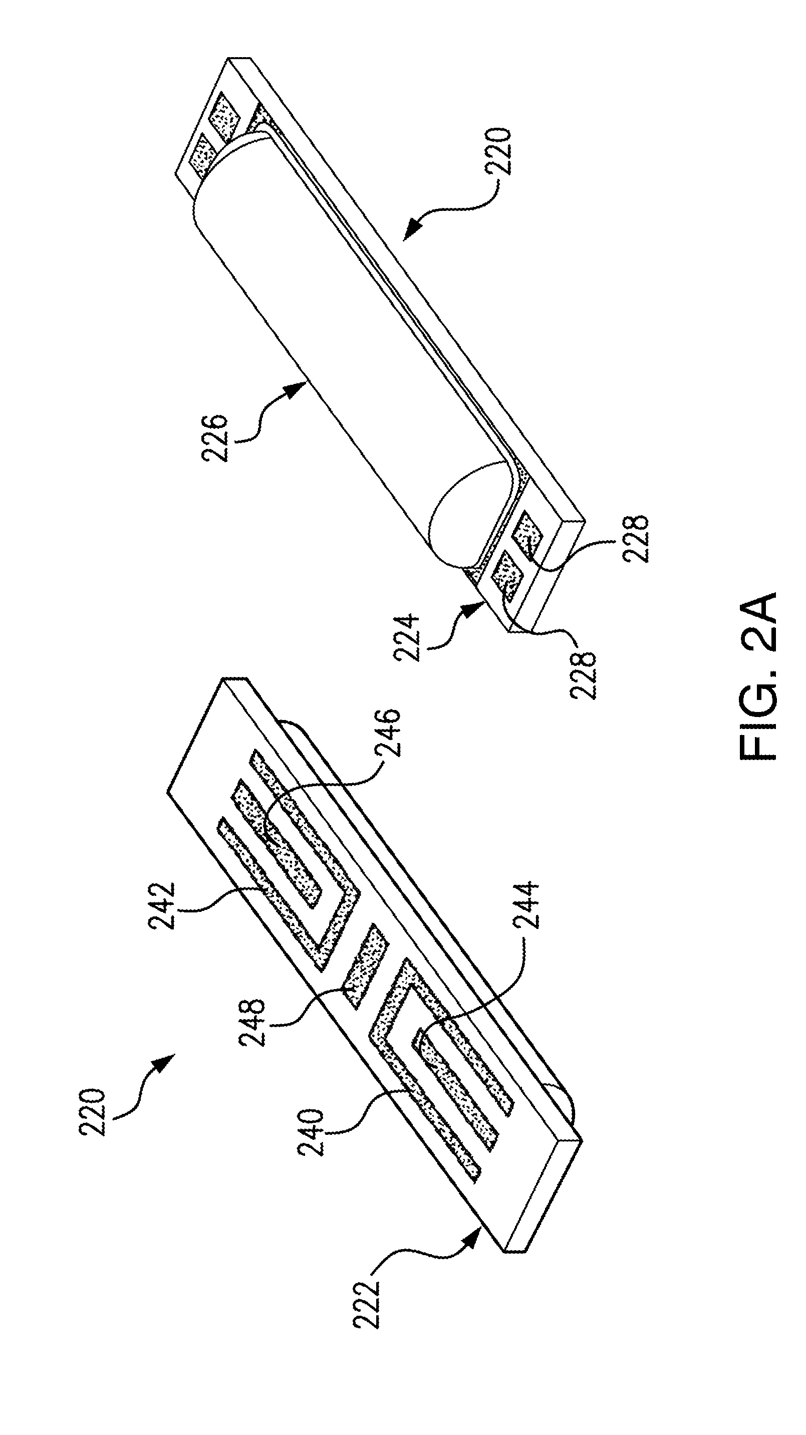
  • Application of electrochemical impedance spectroscopy in sensor systems, devices, and related methods

Examples


second embodiment

[0168]FIG. 14B illustrates a combination of a hydration method and a stabilization method where feedback is utilized in the stabilization process. A sensor is connected 1405 to a sensor electronics device. An AC signal (or a DC signal) is applied 1411 to the sensor. In an embodiment of the invention, the AC signal (or the DC signal) is applied to an electrode of the sensor, e.g. the reference electrode. An impedance measuring device (or resistance measuring device) measures 1416 the impedance (or resistance) within a specified area of the sensor. In an embodiment of the invention, the impedance (or resistance) may be measured between the reference electrode and the working electrode. The measured impedance (or resistance) may be compared 1421 to an impedance or resistance value to see if the impedance (or resistance) is low enough in the sensor, which indicates the sensor is hydrated. If the impedance (or resistance) is below the impedance (or resistance) value or other set criteria...

third embodiment

[0169]FIG. 14C illustrates the invention where a stabilization method and hydration method are combined. In this embodiment of the invention, the sensor is connected 1500 to the sensor electronics device. After the sensor is physically connected to the sensor electronics device, an AC signal (or DC signal) is applied 1510 to an electrode (e.g., reference electrode) of the sensor. At the same time, or around the same time, the microcontroller transmits a signal to cause the DAC to apply 1520 a stabilization voltage sequence to the sensor. In an alternative embodiment of the invention, a stabilization current sequence may be applied to the sensor instead of a stabilization voltage sequence. The detection circuit determines 1530 what level of an AC signal (or DC signal) is present at an input terminal of the detection circuit. If there is a low level AC signal (or DC signal), representing a highly attenuated AC signal (or DC signal), present at the input terminal of the detection circu...


PUM


Abstract

A diagnostic Electrochemical Impedance Spectroscopy (EIS) procedure is applied to measure values of impedance-related parameters for one or more sensing electrodes. The parameters may include real impedance, imaginary impedance, impedance magnitude, and / or phase angle. The measured values of the impedance-related parameters are then used in performing sensor diagnostics, calculating a highly-reliable fused sensor glucose value based on signals from a plurality of redundant sensing electrodes, calibrating sensors, detecting interferents within close proximity of one or more sensing electrodes, and testing surface area characteristics of electroplated electrodes. Advantageously, impedance-related parameters can be defined that are substantially glucose-independent over specific ranges of frequencies. An Application Specific Integrated Circuit (ASIC) enables implementation of the EIS-based diagnostics, fusion algorithms, and other processes based on measurement of EIS-based parameters.

Description

RELATED APPLICATION DATA[0001]This application claims the benefit of U.S. Provisional Application Ser. No. 61 / 755,811, filed Jan. 23, 2013, and of U.S. Provisional Application Ser. No. 61 / 754,475, filed Jan. 18, 2013, and of U.S. Provisional Application Ser. No. 61 / 754,479, filed Jan. 18, 2013, and of U.S. Provisional Application Ser. No. 61 / 754,483, filed Jan. 18, 2013, and of U.S. Provisional Application Ser. No. 61 / 754,485, filed Jan. 18, 2013, and of U.S. Provisional Application Ser. No. 61 / 657,517, filed Jun. 8, 2012, all of which are incorporated herein by reference in their entirety.FIELD OF THE INVENTION[0002]Embodiments of this invention are related generally to methods and systems of using Electrochemical Impedance Spectroscopy (EIS) in conjunction with continuous glucose monitors and, more particularly, to the use of EIS in sensor diagnostics and fault detection, sensor calibration, sensor-signal optimization via one or more fusion algorithms, contaminant / interferent dete...

Claims


Application Information

Patent Timeline
IPC IPC(8): G01R35/00
CPCG01R35/005A61B5/14532A61B5/1459A61B5/1473A61B5/14865A61B5/1495A61B5/7221A61M5/1582A61B5/0537A61B5/746A61M5/14276G01N33/49A61M2005/1726A61M5/14244A61B5/6846G01N27/4163G01R35/00G01N33/66A61B5/14503A61B2562/04A61B5/7225G01N27/416A61M5/1723G01N27/026A61B5/0538A61B5/6849A61B5/7203A61B2562/0214G01N33/96A61B5/7242G01N27/028A61B5/4839A61B5/6852
Inventor WANG, JENN-HANN LARRYMILLER, MICHAEL E.GAUTHAM, RAGHAVENDHARLI, YIWENSHAH, RAJIV
Owner MEDTRONIC MIMIMED INC
Learn More