Even if imaging and / or depth gauging sensors are affixed to the
robot arm, these sensors may be configured for high precision close-up work, and the configuration of the sensors may be unsuitable to determine the
pose of a workpiece, especially if the workpiece is an auto body shell or similarly large object.
These sensors may suffer from limited accuracy, slow operation, limited range of depth measurement, poor suitability for
pose estimation, and other problems.
The conveyor position could be used together with proximity switches and other sensors as described above, but it can be complicated to coordinate and process the data from such a hodge-podge sensorium.
The accuracy of the
pose estimation suffers if the pose is determined using information from an optomechanical
encoder and related sensors.
Significant labor may be required to install and maintain the sensors and the
computer hardware and
software that monitors them.
However, no matter how accurate a 3D sensor may be at the time of its most recent calibration, gravitational pull or vibration or an unintentional bump can cause a sensor to slip, twist, or droop so that the sensor points in a slightly different direction than is intended.
In a manufacturing environment, a 3D sensor will be subject to numerous disturbances such as vibration, changes in temperature, changes in
ambient lighting conditions, and unintentional bumps that can cause persistent or temporary misalignment.
A change in ambient temperature can cause expansion or contraction of components that distort the
optical path of the 3D sensor, and this
distortion will contribute to measurement error.
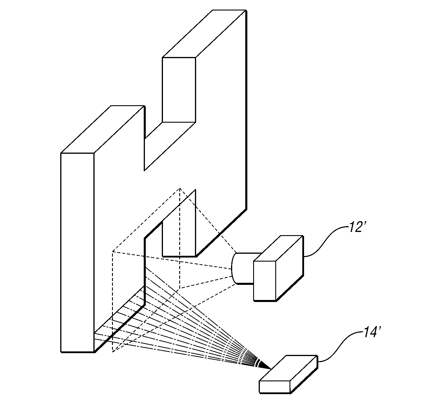
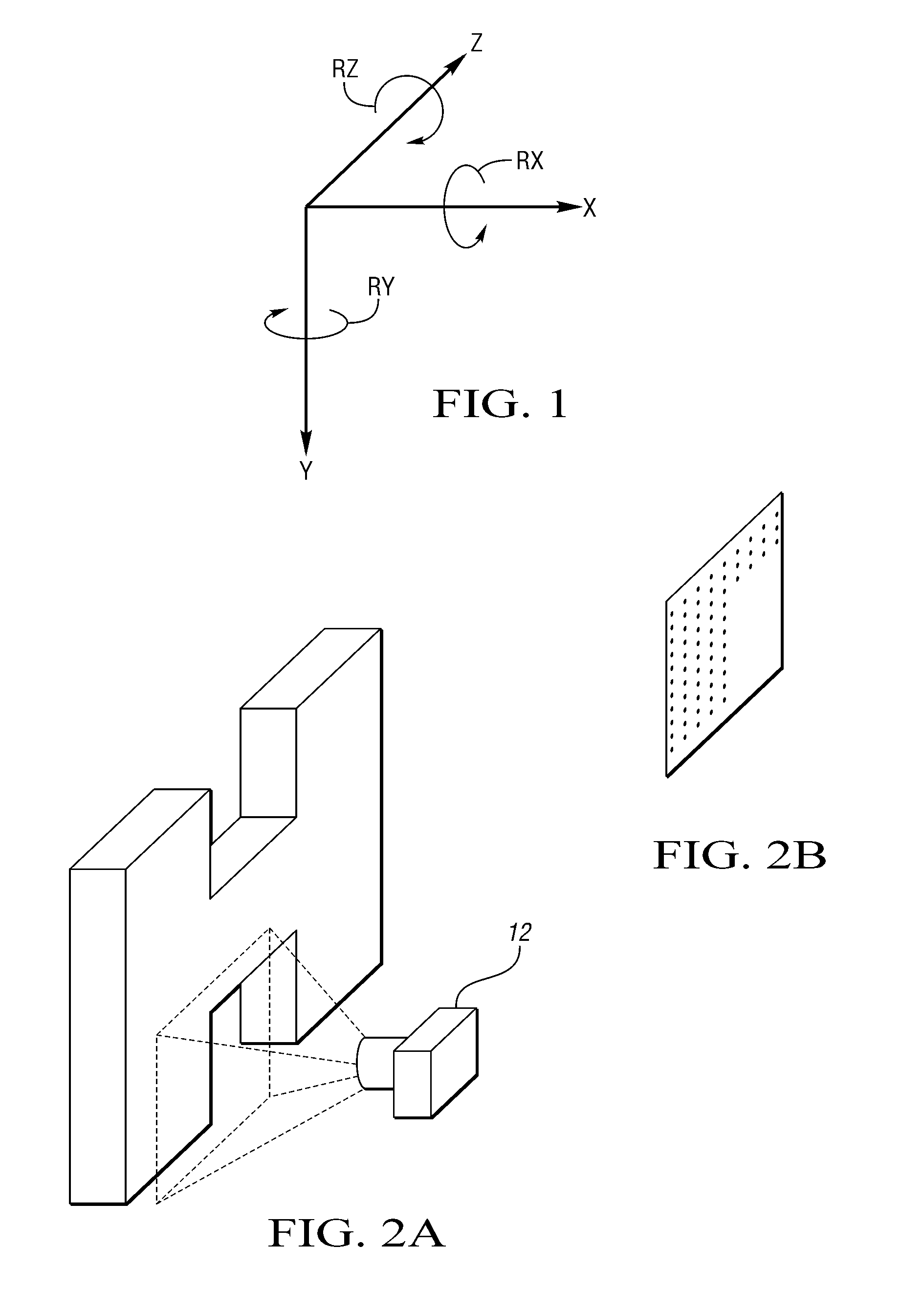
If a 3D sensor is misaligned, then the misalignment will cause unexpected deviations in one or more of the
six degrees of freedom (X,Y,Z,Rx,RY,RZ), and these deviations will adversely affect the accuracy of measurement of the pose of a workpiece.
Periodic calibration and realignment of the sensor can correct misalignment, but inaccuracy of measurement may not be detected until the calibration is performed.
If calibration reveals that the sensor's measurement accuracy is no longer within an acceptable range, it may be difficult or even impossible to determine the time at which the misalignment occurred, or whether the magnitude of measurement error has been constant over time.
Inexpensive commercial 3D sensors may be difficult to recalibrate to ensure long-term accuracy.
Measurement errors can be observed by mounting the Kinect and orienting it so that it images a matte, flat surface perpendicular to the
optical axis of the Kinect.
It is also known, and empirical tests quickly confirm, that random measurement error for Kinect depth data is proportional to the square of the distance from the sensor to the target.
The number and position of these artifacts can change from one depth image to the next, and although the rate of change may slow after the first few minutes of operation, the number and position of the vertical lines may change unpredictably even thereafter.
The artifacts appear as straight vertical lines even if objects or surfaces at different depths
straddle affected columns, since the vertical image artifacts affect the depth measurements for objects in the scene, these image artifacts are considered
sources of error alongside the measurement drift during startup and the sensitivity to ambient temperature.
Although relatively inexpensive 3D sensors such as the Kinect may have acceptable short-term
measurement repeatability on the order of a
millimeter, it is obvious to a practitioner skilled in the art of non-contact dimensional gauging that measurement drift over time and the presence of image artifacts pose problems for measurement applications that demand high accuracy.
Either these low cost sensors must be accepted as inaccurate and thus useful for only the least demanding applications, or the sensors must be
set aside in favor of 3D measurement devices that are more accurate but also more expensive, more complicated to operate, less readily available, and more difficult to maintain.

