
Rotary agitation type heat treatment apparatus

Active Publication Date: 2013-12-12
NISSHIN ENG
View PDF1 Cites 6 Cited by
  • Summary
  • Abstract
  • Description
  • Claims
  • Application Information

AI Technical Summary

Benefits of technology

The patent text describes a rotary agitation type heat treatment apparatus that uses ceramic materials for the agitation members and cylindrical member to prevent contamination in the production of battery materials, particularly positive electrode materials for secondary lithium-ion batteries. The ceramic materials also prevent damage to the apparatus during heat treatment. The ceramic materials used allow for efficient heat treatment and reduced production costs and CO2 emissions, while also contributing to global environmental conservation. The technical effect of the patent is to provide a safer and efficient method for producing high-quality battery materials.

Problems solved by technology

However, ceramic materials have a drawback of having a lower mechanical impact strength and a lower thermal shock strength than metal materials.
More specifically, where an agitation member having two or more blades is made of a ceramic material, the shaft structure or the edge portions of the blades are liable to suffer damage from the impact with which the edge portions of the blades of the ceramic agitation member hit the inner wall of the ceramic rotary cylindrical member.
In this case, the ceramic rotary cylindrical member also has an increased chance of being damaged.
When the thickness of the shaft structure of a ceramic agitation member is increased in order to increase the mechanical strength of the shaft structure of the ceramic agitation member, the weight of the agitation member in turn increases, and so does the weight load onto the rotary cylindrical member accordingly, increasing the impulsive force and thereby increasing the risk of the ceramic rotary cylindrical member being damaged.

Method used

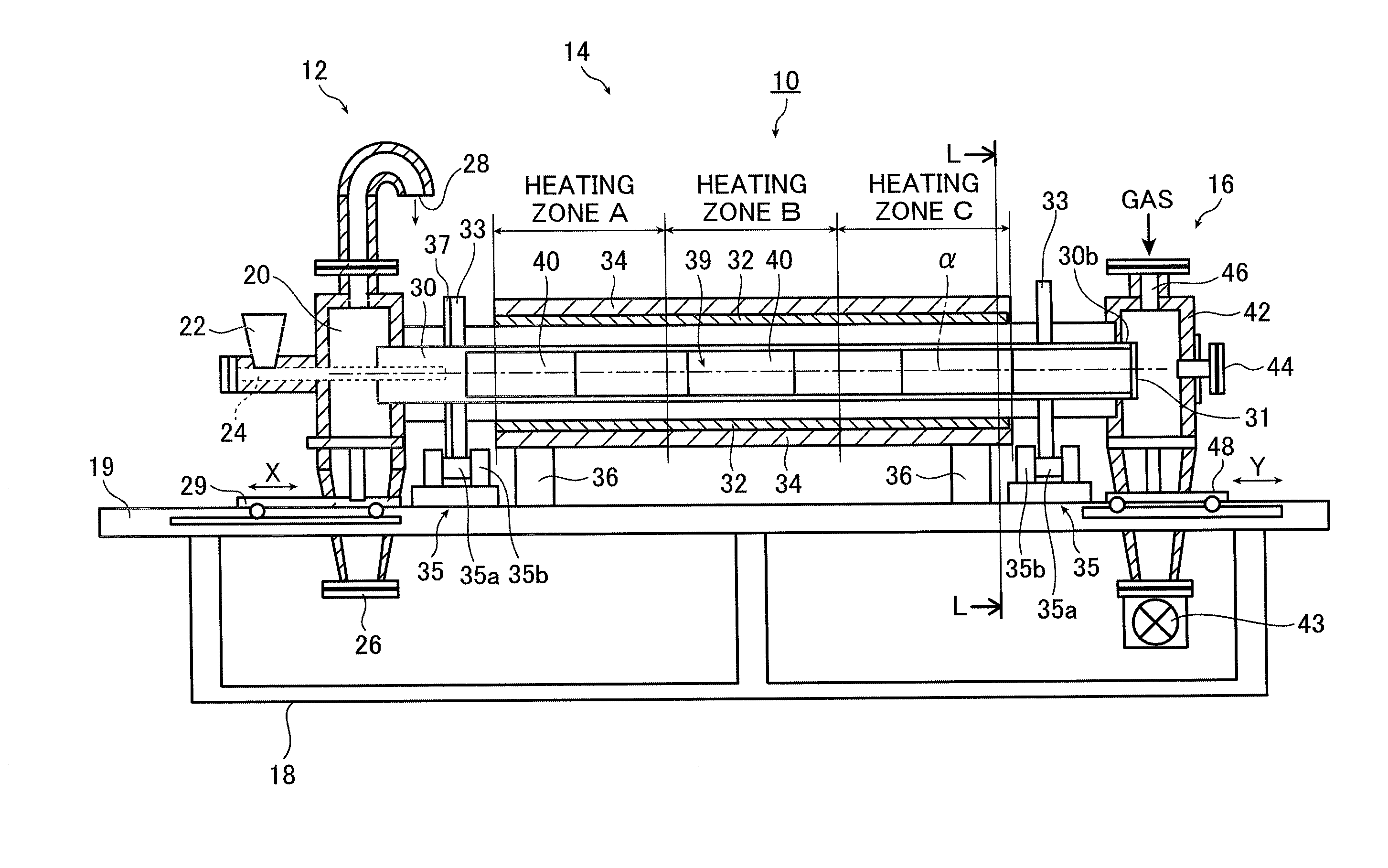
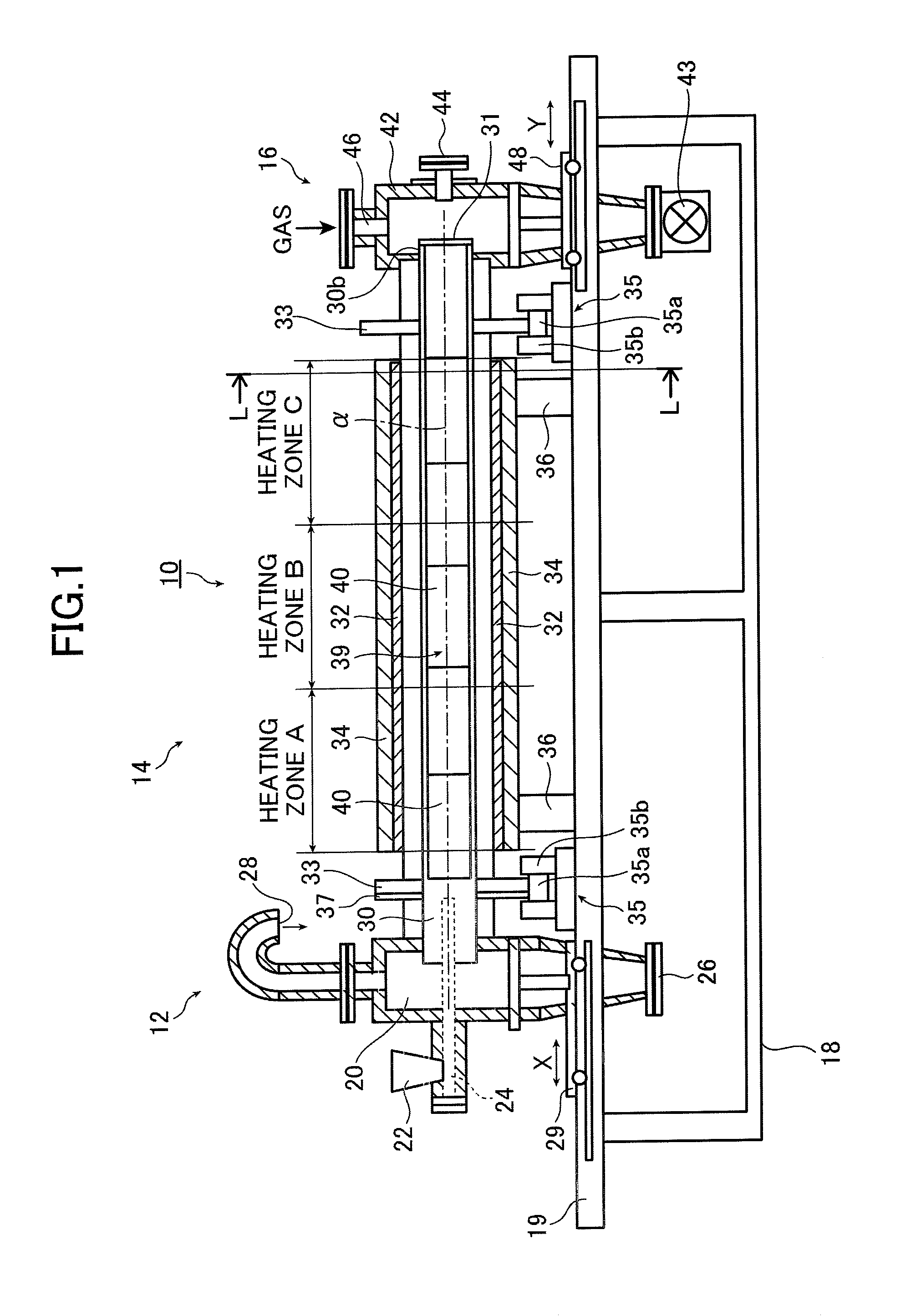
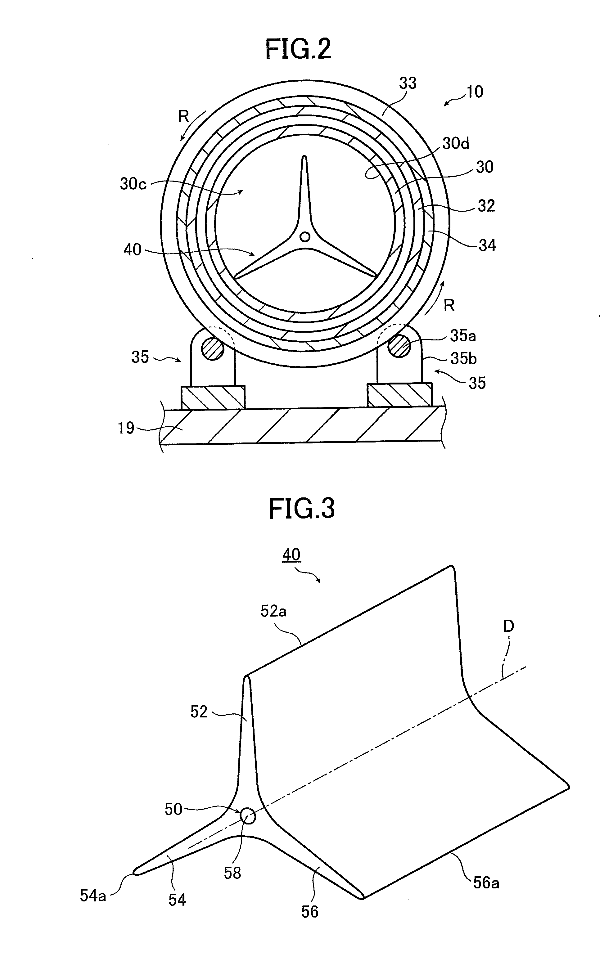

Image

  • Rotary agitation type heat treatment apparatus
  • Rotary agitation type heat treatment apparatus
  • Rotary agitation type heat treatment apparatus

Examples


example

[0128]An example of the rotary agitation type heat treatment apparatus of the present invention is illustrated below.

[0129]In the example, raw materials for a positive electrode material for secondary lithium-ion batteries were used as the material to be treated, so as to produce the positive electrode material for secondary lithium-ion batteries.

[0130]The raw materials as used for the positive electrode material for secondary lithium-ion batteries were lithium carbonate (Li2CO3) and manganese dioxide (MnO2). Lithium carbonate and manganese dioxide were combined together at a molar ratio of 1:1 and mixed, and the mixture was granulated. After sieving, granulated powder having such a particle size composition that particles with a diameter of not more than 0.25 mm comprise up to 20 wt % of the whole powder was finally obtained, and used as the material to be treated.

[0131]During the granulation, Roller Compactor model WP (manufactured by Turbo Kogyo Co., Ltd.) was used to conduct con...


PUM


Abstract

A rotary agitation type heat treatment apparatus includes: a cylindrical member for performing heat treatment on a material to be treated supplied inside the cylindrical member from one end thereof; a rotating unit for rotating the cylindrical member; a heating unit for heating the material supplied inside the cylindrical member; and agitation members arranged in the cylindrical member. Each agitation member has a shaft structure and two or more blades provided on the shaft structure. The cylindrical member and the agitation members are constituted of a ceramic material. The material inside the cylindrical member is heated and the cylindrical member is rotated, so that the material is heat treated while agitated by the agitation members in the cylindrical member, and discharged out from the other end thereof.

Description

BACKGROUND OF THE INVENTION[0001]The present invention relates to a rotary agitation type heat treatment apparatus (rotary kiln) that performs agitating and heating treatment, as it rotates, on a material to be treated (which may be referred to as subject material below) and in particular to a rotary agitation type heat treatment apparatus wherein a rotary cylindrical member through which the subject material passes and agitation members disposed in the rotary cylindrical member to agitate the subject material are made of ceramic materials.[0002]There is known in the art a rotary agitation type heat treatment apparatus having a metallic agitation member (blade member having radially extending blades, which may be hereinafter referred to as blade member) disposed inside a metallic rotary cylindrical member for agitation of a subject material or other purposes (see, for example, JP 2000-42437 A).[0003]JP 2000-42437 A describes a crushing / pulverizing / sizing apparatus comprising inside ...

Claims


Application Information

Patent Timeline
IPC IPC(8): B01F9/02B01F15/06B01F29/60
CPCF27B7/14
Inventor KATAKURA, MASAYUKISUZUKI, HIROMITSUGOTO, TAKAHIRO
Owner NISSHIN ENG
Learn More